CAMSHAFT REMOVAL

-
REMOVE FRONT WHEEL RH
-
REMOVE FRONT WHEEL OPENING EXTENSION PAD RH
-
REMOVE ENGINE UNDER COVER RH
-
REMOVE FRONT FENDER APRON SEAL RH
-
REMOVE NO. 1 ENGINE COVER SUB-ASSEMBLY
-
Lift the rear of the engine cover to detach the cover from the 2 pins, and then lift the front of the engine cover to detach the cover from the pin and remove the No. 1 engine cover sub-assembly.
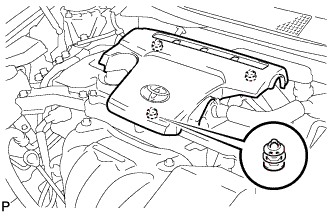
Note
Attempting to disengage both front and rear clips at the same time may cause the No. 1 engine cover sub-assembly to break.
-
-
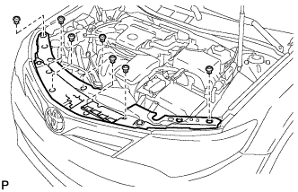
REMOVE COOL AIR INTAKE DUCT SEAL
-
Remove the 7 clips and cool air intake duct seal.
-
-
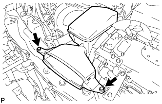
REMOVE INLET AIR CLEANER ASSEMBLY
-
Remove the 2 bolts and inlet air cleaner assembly.
-
-
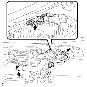
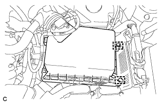
REMOVE AIR CLEANER CAP SUB-ASSEMBLY
-
Disconnect the mass air flow meter connector and wire harness clamp from the air cleaner cap sub-assembly.
-
Disconnect the ventilation hose from the cylinder head cover.
-
Disconnect the connector and wire harness clamp.
-
Release the 2 clamps and remove the air cleaner cap sub-assembly.
-
Disconnect the 2 fuel vapor feed hoses.
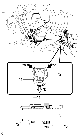
Text in Illustration *1 Retainer *2 Fuel Tube Connector *3 Pipe *4 O-ring *a Pinch *b Pull Note
-
Remove any dirt or foreign matter on the fuel tube connector before performing this work.
-
Do not allow any scratches or foreign matter to get on the parts when disconnecting them as the fuel tube connector has an O-ring that seals the pipe.
-
Perform this work by hand. Do not use any tools.
-
Protect the disconnected parts by covering them with plastic bags after disconnecting each fuel vapor feed hose.
-
-
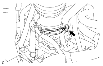
Loosen the hose clamp and disconnect the air cleaner hose from the throttle with motor body assembly.
-
-
REMOVE AIR CLEANER FILTER ELEMENT
-
Remove the air cleaner filter element.
-
-
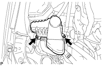
REMOVE AIR CLEANER CASE SUB-ASSEMBLY
-
Remove the 2 bolts and air cleaner case sub-assembly.
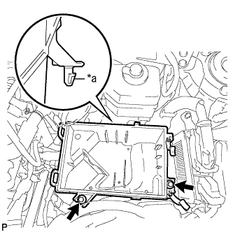
Text in Illustration *a Projection
-
-
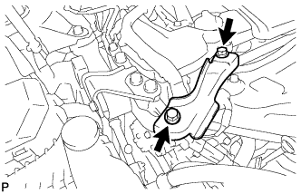
REMOVE NO. 2 ENGINE MOUNTING STAY RH
-
Remove the 2 bolts and No. 2 engine mounting stay RH.
-
-
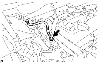
DISCONNECT EARTH WIRE
-
Remove the bolt and separate the earth wire from the engine moving control rod bracket.
-
-
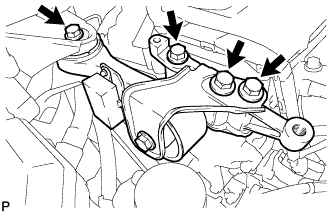
REMOVE ENGINE MOVING CONTROL ROD SUB-ASSEMBLY
-
Remove the 4 bolts and engine moving control rod sub-assembly.
-
-
DISCONNECT INVERTER RESERVE TANK ASSEMBLY (for LHD)
-
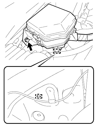
Remove the 2 bolts and disconnect the inverter reserve tank assembly.
-
-
DISCONNECT NO. 2 ENGINE ROOM RELAY BLOCK (for LHD)
-
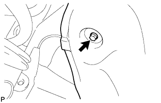
Remove the screw and disconnect the front fender liner RH.
-
Remove the bolt, harness clamp and disconnect the No. 2 engine room relay block.
-
-
DISCONNECT ENGINE WIRE
-
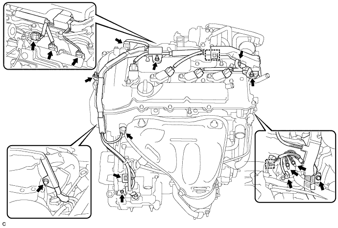
Disconnect the 8 connectors and 2 harness clamps.
-
Remove the 5 bolts and 3 nuts and disconnect the engine wire from the engine.
-
-
REMOVE IGNITION COIL ASSEMBLY
-
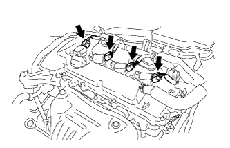
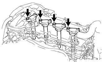
Disconnect the 4 ignition coil assembly connectors.
-
Remove the 4 bolts and 4 ignition coil assemblies.
-
-
REMOVE CYLINDER HEAD COVER SUB-ASSEMBLY
-
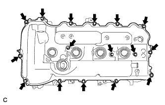
Remove the 16 bolts, 3 seal washers, cylinder head cover sub-assembly and cylinder head cover gasket.
-
Remove the 2 gaskets from the camshaft bearing caps.
-
-
SET NO. 1 CYLINDER TO TDC/COMPRESSION
-
Turn the crankshaft pulley until its timing notch (groove) and the timing mark "0" of the timing chain cover are aligned.
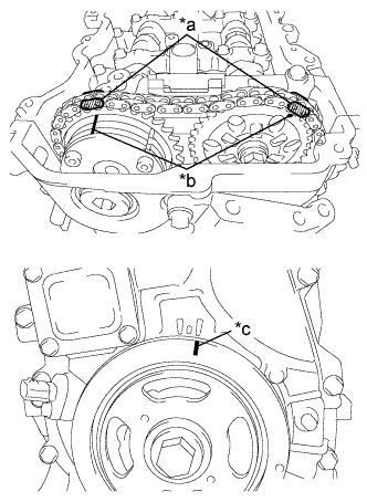
Text in Illustration *a Paint Mark *b Timing Mark *c Timing Notch -
Check that each timing mark of the camshaft timing gear assembly and camshaft timing sprocket are aligned with each timing mark located as shown in the illustration. If not, turn the crankshaft 1 revolution (360°) to align the timing marks as shown in the illustration.
-
Place paint marks on the chain in alignment with the timing marks on the camshaft timing gear and camshaft timing sprocket.
-
-
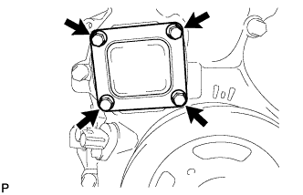
REMOVE TIMING CHAIN COVER PLATE
-
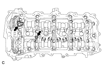
Remove the 4 bolts, timing chain cover plate and gasket.
-
-
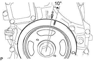
REMOVE NO. 1 CHAIN TENSIONER ASSEMBLY
-
Turn the crankshaft approximately 10° clockwise.
-
Turn the crankshaft approximately 10° counterclockwise.
-
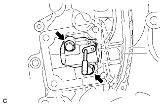
Align the holes of the stopper plate and tensioner, and insert a pin into the stopper plate hole to lock the tensioner.
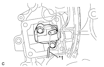
Text in Illustration *1 Pin -
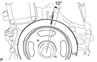
Turn the crankshaft approximately 10° clockwise.
-
Remove the 2 bolts, chain tensioner and gasket.
Note
Make sure not to drop the gasket inside the timing chain cover.
-
Turn the crankshaft approximately 10° counterclockwise.
-
-
REMOVE TIMING CHAIN GUIDE
-
Remove the bolt and timing chain guide.
-
-
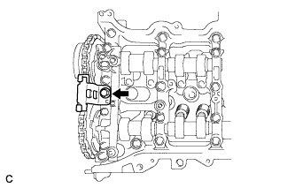
REMOVE OIL PUMP RELIEF VALVE PLUG
-
Using a 14 mm hexagon wrench, remove the oil pump relief valve plug and gasket.
-
-
REMOVE CAMSHAFT TIMING GEAR ASSEMBLY
-
Hold the hexagonal portion of the camshaft with a wrench and remove the bolt from the camshaft.
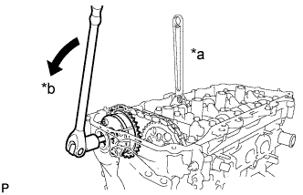
Text in Illustration *a Hold *b Turn Note
Be careful not to damage the cylinder head or spark plug tube with the wrench.
-
Separate the camshaft timing gear assembly from the camshaft.
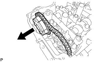
-
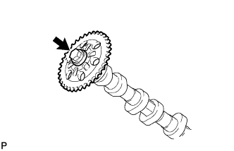
Remove the timing chain from the camshaft timing gear assembly, and turn the camshaft timing gear assembly approximately 180°.
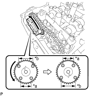
Text in Illustration *a Narrow *b Wide -
Remove the camshaft timing gear assembly.
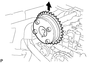
Note
Do not disassemble the camshaft timing gear.
-
-
REMOVE CAMSHAFT BEARING CAP
-
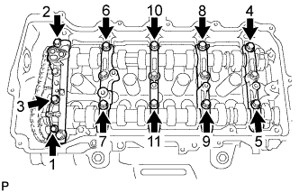
Using several steps, remove the 11 bearing cap bolts in the sequence shown in the illustration.
-
Using several steps, remove the 10 bearing cap bolts in the sequence shown in the illustration.
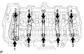
-
Remove the 5 bearing caps.
Tech Tips
Arrange the removed parts in the correct order.
-
-
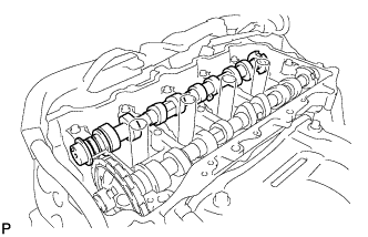
REMOVE CAMSHAFT
-
Remove the camshaft from the camshaft housing.
-
-
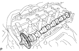
REMOVE NO. 2 CAMSHAFT
-
Hold up the chain and remove the No. 2 camshaft from the camshaft housing.
-
Suspend the chain with a string or equivalent as shown in the illustration.
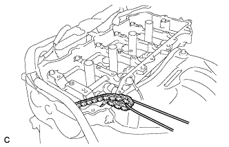
Note
Be careful not to drop the chain inside the timing chain cover.
-
-
REMOVE CAMSHAFT TIMING SPROCKET
-
Secure the camshaft in a vice by clamping the hexagonal part using aluminum plates.
Note
Do not damage the camshaft by tightening the vice excessively.
-
Remove the flange bolt and camshaft timing sprocket.
Note
Do not damage the No. 2 camshaft or camshaft timing sprocket.
-
-
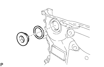
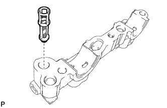
REMOVE OIL CONTROL VALVE FILTER
-
Remove the oil control valve filter from the No. 1 camshaft bearing cap.
-
-
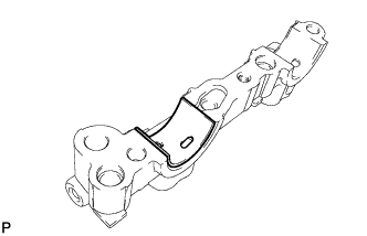
REMOVE NO. 1 CAMSHAFT BEARING
-
Remove the No. 1 camshaft bearing from the No. 1 camshaft bearing cap.
-
-
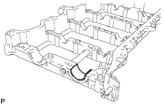
REMOVE NO. 2 CAMSHAFT BEARING
-
Remove the No. 2 camshaft bearing from the camshaft housing sub-assembly.
-