FRAME WIRE INSTALLATION

-
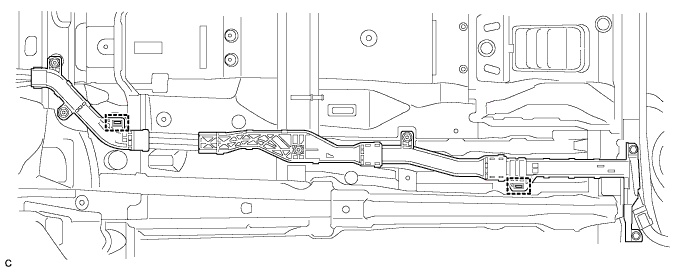
INSTALL NO. 4 FLOOR WIRE
CAUTION:
Wear insulated gloves.
-
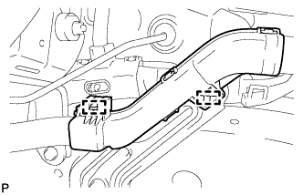
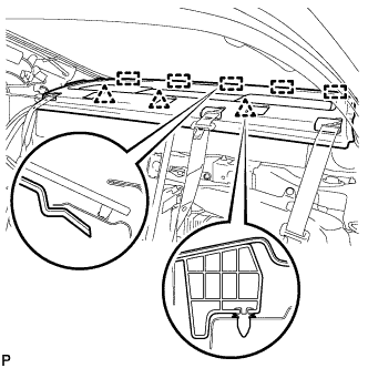
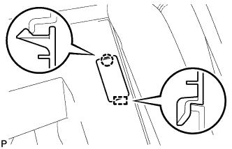
Install the No. 4 floor wire with 2 new clamps shown in the illustration.
-
Install the 4 nuts and 2 bolts shown in the illustration.
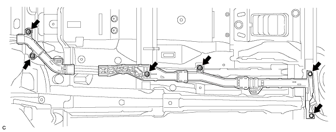
- Torque:
- 8.0 N*m { 82 kgf*cm, 71 in.*lbf }
-
Install the 2 bolts shown in the illustration.
- Torque:
- 8.0 N*m { 82 kgf*cm, 71 in.*lbf }
-
Install the 2 nuts shown in the illustration.
- Torque:
- 8.0 N*m { 82 kgf*cm, 71 in.*lbf }
-
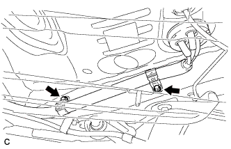
Connect the connector and 2 wire harness clamps.
-
Connect the 2 wire harness clamps shown in the illustration.
-
Insert the No. 4 floor wire into the floor panel hole.
-
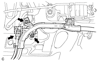
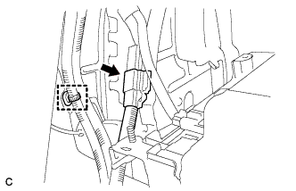
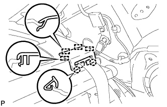
Connect the connector and wire harness clamp.
-
Connect the 2 connectors.
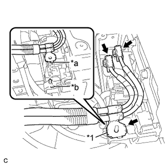
Text in Illustration *1 Shielded Wire Ground *a Claw *b Hole -
Connect the shielded wire ground.
Note
-
Make sure that the ends of the No. 4 floor wire do not cross over each other.
-
The connector should be connected securely.
-
Be sure to align the claw of the shielded wire ground with the hole.
-
Be sure to install the shielded wire ground in the correct direction.
-
-
-
INSTALL NO. 4 HYBRID BATTERY SHIELD PANEL
CAUTION:
Wear insulated gloves.
-
Install the No. 4 hybrid battery shield panel with the bolt and 2 nuts.
- Torque:
- 7.5 N*m { 76 kgf*cm, 66 in.*lbf }
-
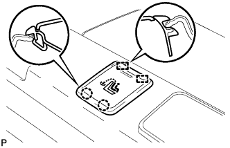
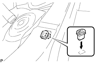
Install the battery cover lock striker, then push the button to lock it.
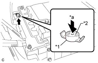
Text in Illustration *1 Battery Cover Lock Striker *2 Button *a Push
-
-
INSTALL NO. 1 FLOOR UNDER COVER
-
Install the No. 1 floor under cover with the 2 bolts, 3 nuts and 2 clips.
- Torque:
- Bolt
- 12 N*m { 122 kgf*cm, 9 ft.*lbf }
- Nut
- 4.0 N*m { 41 kgf*cm, 35 in.*lbf }
-
-
INSTALL FRONT CENTER FLOOR COVER RH
-
Install the front center floor cover RH with the 6 clips.
-
-
INSTALL NO. 2 PARKING BRAKE CABLE ASSEMBLY
-
Install the No. 2 parking brake cable assembly with the nut.
- Torque:
- 6.0 N*m { 61 kgf*cm, 53 in.*lbf }
-
-
INSTALL NO. 1 ROOM PARTITION BOARD
-
Engage the 5 clips to install the No. 1 room partition board.
-
Install the 4 clips.
-
-
INSTALL PACKAGE TRAY TRIM PANEL ASSEMBLY
-
Pass the 3 rear seat belt floor anchors through the package tray trim panel assembly.
-
Engage the 5 guides and 3 clips to install the package tray trim panel assembly.
-
-
INSTALL REAR SEAT SHOULDER BELT COVER
-
Engage the 4 guides and 2 claws to install the rear seat shoulder belt cover.
Tech Tips
Use the same procedure for the other 2 rear seat shoulder belt covers.
-
-
INSTALL CHILD RESTRAINT SEAT TETHER ANCHOR COVER
-
Engage the 2 guides and 2 claws to install the child restraint seat tether anchor cover.
Tech Tips
Use the same procedure for the other 2 child restraint seat tether anchor covers.
-
-
INSTALL CENTER STOP LIGHT SET
-
Connect the connector.
-
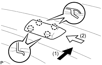
Temporarily install the center stop light set.
-
Slide the center stop light set in the order and directions shown by the arrows in the illustration while pushing it towards the rear of the vehicle to engage the 4 claws.
-
-
INSTALL ROOF SIDE INNER GARNISH LH
-
Engage the guide.
-
Engage the 5 clips to install the roof side inner garnish LH.
-
-
INSTALL ROOF SIDE INNER GARNISH RH
Tech Tips
Use the same procedure as for the LH side.
-
CONNECT REAR SEAT INNER WITH CENTER BELT ASSEMBLY LH
-
Engage the guide to temporarily install the rear seat inner with center belt assembly LH.
-
Install the bolt.
- Torque:
- 42 N*m { 428 kgf*cm, 31 ft.*lbf }
-
Check if the ELR locks.
Note
The check should be performed with the rear seat inner with center belt assembly LH installed.
-
With the belt assembly installed, check that the belt locks when it is pulled out quickly.
-
-
-
INSTALL CHILD RESTRAINT SEAT ANCHOR BRACKET SUB-ASSEMBLY LH
-
Install the child restraint seat anchor bracket sub-assembly LH with the 2 nuts.
- Torque:
- 18 N*m { 184 kgf*cm, 13 ft.*lbf }
-
-
CONNECT REAR SEAT OUTER BELT ASSEMBLY (for LH Side)
-
Connect the floor anchor of the rear seat outer belt assembly with the bolt.
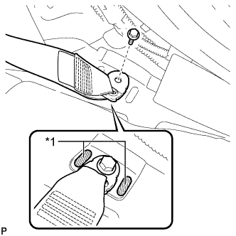
Text in Illustration *1 Protruding Part - Torque:
- 42 N*m { 428 kgf*cm, 31 ft.*lbf }
Note
Do not allow the anchor part of the rear seat outer belt assembly to overlap the protruding parts of the floor panel.
-
-
CONNECT REAR SEAT OUTER BELT ASSEMBLY (for RH Side)
-
Connect the floor anchor of the rear seat outer belt assembly with the bolt.
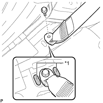
Text in Illustration *1 Protruding Part - Torque:
- 42 N*m { 428 kgf*cm, 31 ft.*lbf }
Note
Do not allow the anchor part of the rear seat outer belt assembly to overlap the protruding parts of the floor panel.
-
-
INSTALL REAR DOOR OPENING TRIM WEATHERSTRIP LH
-
Align the alignment mark (Pink) on the weatherstrip with the protruding portion on the body indicated by the arrow in the illustration, and install the rear door opening trim weatherstrip LH.
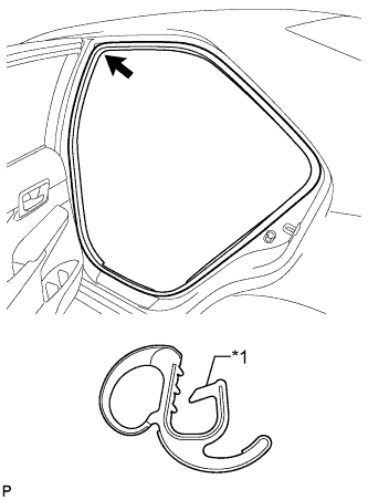
Text in Illustration *1 Alignment Mark (Pink) Note
After installation, check that the corners fit correctly.
-
-
INSTALL REAR DOOR OPENING TRIM WEATHERSTRIP RH
-
Align the alignment mark (Blue) on the weatherstrip with the protruding portion on the body indicated by the arrow in the illustration, and install the rear door opening trim weatherstrip RH.
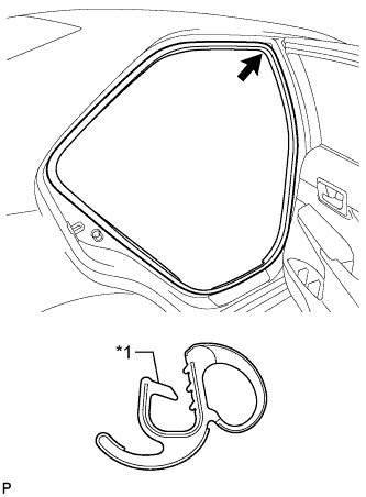
Text in Illustration *1 Alignment Mark (Blue) Note
After installation, check that the corners fit correctly.
-
-
INSTALL REAR SIDE SEATBACK ASSEMBLY LH
-
Engage the hook to install the rear side seatback assembly LH.
-
Install the 2 bolts.
- Torque:
- 18 N*m { 184 kgf*cm, 13 ft.*lbf }
-
Connect the connector.
-
Connect the rear seat outer belt to the rear seat shoulder belt guide LH.
-
-
INSTALL REAR SIDE SEATBACK ASSEMBLY RH
-
Engage the hook to install the rear side seatback assembly RH.
-
Install the 2 bolts.
- Torque:
- 18 N*m { 184 kgf*cm, 13 ft.*lbf }
-
Connect the connector.
-
Connect the rear seat outer belt to the rear seat shoulder belt guide RH.
-
-
INSTALL REAR SEATBACK ASSEMBLY LH
-
Place the rear seatback assembly LH in the cabin.
Note
Be careful not to damage the vehicle body.
-
Install the rear seatback assembly LH with the 2 bolts.
- Torque:
- 18 N*m { 184 kgf*cm, 13 ft.*lbf }
-
Connect the rear seat inner with center belt assembly LH to the rear seat center shoulder belt guide.
-
-
INSTALL NO. 2 ROOM PARTITION COVER
-
Engage the guide and claw to install the No. 2 room partition cover.
-
-
INSTALL REAR SEATBACK ASSEMBLY RH
-
Place the rear seatback assembly RH in the cabin.
Note
Be careful not to damage the vehicle body.
-
Install the rear seatback assembly RH with the 2 bolts.
- Torque:
- 18 N*m { 184 kgf*cm, 13 ft.*lbf }
-
-
INSTALL REAR SEAT CUSHION LOCK HOOK
-
Engage the claw to install a new rear seat cushion lock hook.
Note
Rear seat cushion lock hooks must not be reused.
Tech Tips
Use the same procedure for the RH side and the LH side.
-
-
INSTALL REAR SEAT CUSHION ASSEMBLY
-
Place the rear seat cushion assembly in the cabin.
Note
Be careful not to damage the vehicle body.
-
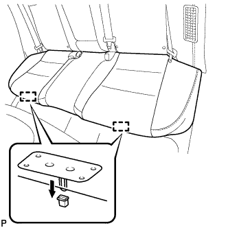
Engage the 2 hooks of the seat cushion to the vehicle body as shown in the illustration.
-
Confirm that the seat cushion is firmly installed.
Note
When installing the seat cushion, make sure that the seat belt buckles are not under the seat cushion.
-
-
INSTALL ENGINE ASSEMBLY WITH TRANSAXLE