FRAME WIRE REMOVAL

-
REMOVE ENGINE ASSEMBLY WITH TRANSAXLE
-
REMOVE REAR SEAT CUSHION ASSEMBLY
-
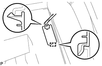
Disengage the hook of the seat cushion from the vehicle body as shown in the illustration.
Note
Follow the instructions below carefully as the cushion frame can be deformed easily.
-
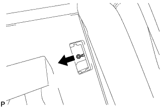
Choose a hook to disengage first. Place your hands near the hook as shown in the illustration. Then lift the seat cushion to disengage the hook.
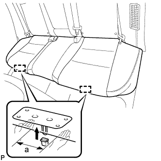
Standard Measurement a 100 mm (3.94 in.) or less -
Repeat the step above for the other hook.
-
-
Remove the rear seat cushion assembly.
-
-
REMOVE REAR SEAT CUSHION LOCK HOOK
-
Disengage the claw and remove the rear seat cushion lock hook.
Note
Rear seat cushion lock hooks must not be reused.
Tech Tips
Use the same procedure for the RH side and the LH side.
-
-
REMOVE REAR SEATBACK ASSEMBLY RH
-
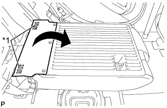
Fold down the rear seatback assembly RH.
-
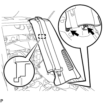
Disengage the 3 fasteners as shown in the illustration.
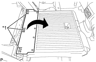
Text in Illustration *1 Fastener -
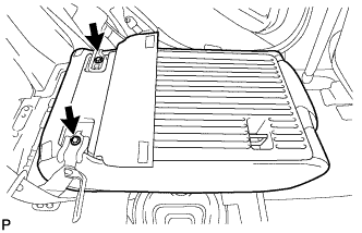
Remove the 2 bolts and rear seatback assembly RH.
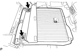
Note
Be careful not to damage the vehicle body.
-
-
REMOVE NO. 2 ROOM PARTITION COVER
-
Using a moulding remover, disengage the claw and guide, and remove the No. 2 room partition cover.
-
-
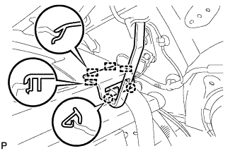
REMOVE REAR SEATBACK ASSEMBLY LH
-
Disconnect the rear seat inner with center belt assembly LH from the rear seat center shoulder belt guide.
-
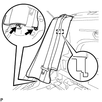
Pull the cable in the direction shown in the illustration to release the rear seatback lock and then fold the rear seatback assembly LH forward.
-
Disengage the 2 fasteners as shown in the illustration.
Text in Illustration *1 Fastener -
Remove the 2 bolts and rear seatback assembly LH.
Note
Be careful not to damage the vehicle body.
-
-
REMOVE REAR SIDE SEATBACK ASSEMBLY LH
-
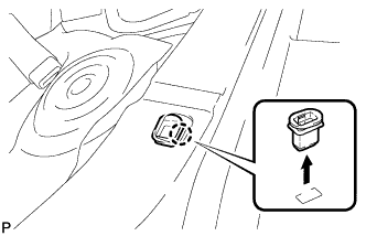
Disconnect the rear seat outer belt from the rear seat shoulder belt guide LH.
-
Disconnect the connector.
-
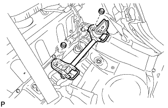
Remove the 2 bolts.
-
Disengage the hook and remove the rear side seatback assembly LH.
-
-
REMOVE REAR SIDE SEATBACK ASSEMBLY RH
-
Disconnect the rear seat outer belt from the rear seat shoulder belt guide RH.
-
Disconnect the connector.
-
Remove the 2 bolts.
-
Disengage the hook and remove the rear side seatback assembly RH.
-
-
DISCONNECT REAR DOOR OPENING TRIM WEATHERSTRIP LH
-
Disconnect the rear door opening trim weatherstrip LH.
-
-
DISCONNECT REAR DOOR OPENING TRIM WEATHERSTRIP RH
-
Disconnect the rear door opening trim weatherstrip RH.
-
-
DISCONNECT REAR SEAT OUTER BELT ASSEMBLY (for LH Side)
-
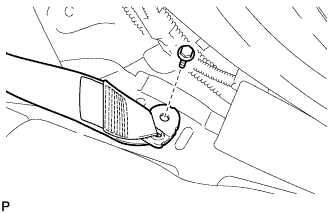
Remove the bolt and disconnect the floor anchor of the rear seat outer belt assembly.
-
-
DISCONNECT REAR SEAT OUTER BELT ASSEMBLY (for RH Side)
-
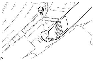
Remove the bolt and disconnect the floor anchor of the rear seat outer belt assembly.
-
-
REMOVE CHILD RESTRAINT SEAT ANCHOR BRACKET SUB-ASSEMBLY LH
-
Remove the 2 nuts and child restraint seat anchor bracket sub-assembly LH.
-
-
DISCONNECT REAR SEAT INNER WITH CENTER BELT ASSEMBLY LH
-
Remove the bolt and disconnect the floor anchor of the rear seat inner with center belt assembly LH.
-
-
REMOVE ROOF SIDE INNER GARNISH LH
-
Disengage the 5 clips.
-
Disengage the guide and remove the roof side inner garnish LH.
-
-
REMOVE ROOF SIDE INNER GARNISH RH
Tech Tips
Use the same procedure as for the LH side.
-
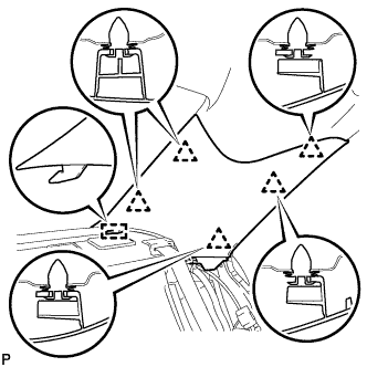
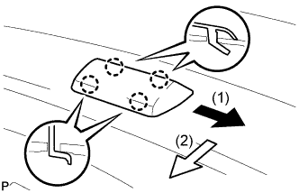
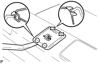
REMOVE CENTER STOP LIGHT SET
-
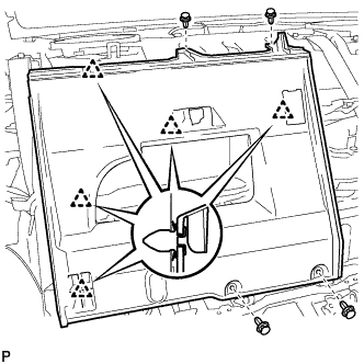
Slide the center stop light set in the order and directions shown by the arrows in the illustration while pushing it towards the rear of the vehicle to disengage the 4 claws.
-
Turn the center stop light set 180 degrees as shown by the arrow in the illustration.
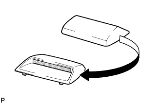
Tech Tips
This makes it easier to disconnect the connector.
-
Disconnect the connector and remove the center stop light set.
-
-
REMOVE CHILD RESTRAINT SEAT TETHER ANCHOR COVER
-
Using a moulding remover, disengage the 2 claws and 2 guides to remove the child restraint seat tether anchor cover.
Tech Tips
Use the same procedure for the other 2 child restraint seat tether anchor covers.
-
-
REMOVE REAR SEAT SHOULDER BELT COVER
-
Using a moulding remover, disengage the 2 claws and 4 guides and remove the rear seat shoulder belt cover.
Tech Tips
Use the same procedure for the other 2 rear seat shoulder belt covers.
-
-
REMOVE PACKAGE TRAY TRIM PANEL ASSEMBLY
-
Using pliers, disengage the 3 clips from inside the luggage compartment as shown in the illustration.
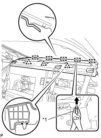
Text in Illustration *1 Protective Tape Tech Tips
Tape the tip of the pliers before use.
-
Disengage the 5 guides.
-
Pass the 3 rear seat belt floor anchors through the package tray trim panel assembly then remove the package tray trim panel assembly.
-
-
REMOVE NO. 1 ROOM PARTITION BOARD
-
Using a clip remover, remove the 4 clips.
-
Disengage the 5 clips and remove the No. 1 room partition board.
-
-
REMOVE NO. 1 FLOOR UNDER COVER
-
Remove the 2 bolts.
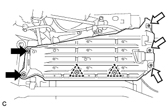
Text in Illustration 
Bolt 
Nut (attached to under cover) -
Disengage the 3 nuts and 2 clips, and remove the No. 1 floor under cover.
-
-
REMOVE FRONT CENTER FLOOR COVER RH
-
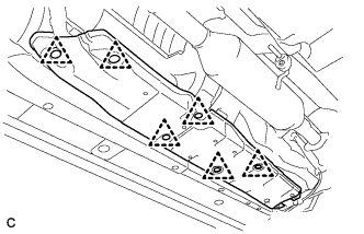
Remove the 6 clips and front center floor cover RH.
-
-
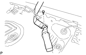
REMOVE NO. 2 PARKING BRAKE CABLE ASSEMBLY
-
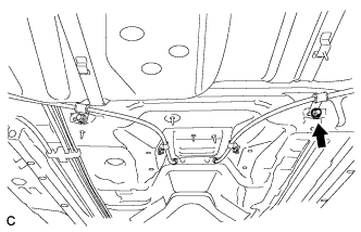
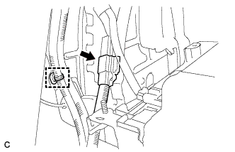
Remove the nut and disconnect the No. 2 parking brake cable assembly.
-
-
REMOVE NO. 4 HYBRID BATTERY SHIELD PANEL
CAUTION:
Wear insulated gloves.
-
Using the service plug grip, remove the battery cover lock striker.
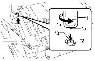
Text in Illustration *1 Service Plug Grip *2 Battery Cover Lock Striker *3 Button *a Projection *b Turn Tech Tips
Insert the projecting part of the service plug grip, and turn the button of the battery cover lock striker counterclockwise to release the lock.
-
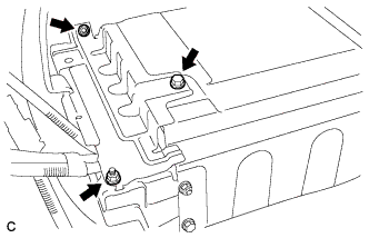
Remove the bolt, 2 nuts and No. 4 hybrid battery shield panel.
-
-
REMOVE NO. 4 FLOOR WIRE
CAUTION:
Wear insulated gloves.
Note
Insulate the removed terminals with insulating tape.
-
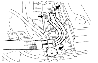
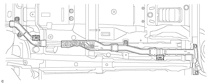
Disconnect the 2 connectors.
-
Disconnect the shielded wire ground.
-
Disconnect the wire harness clamp and connector.
-
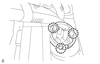
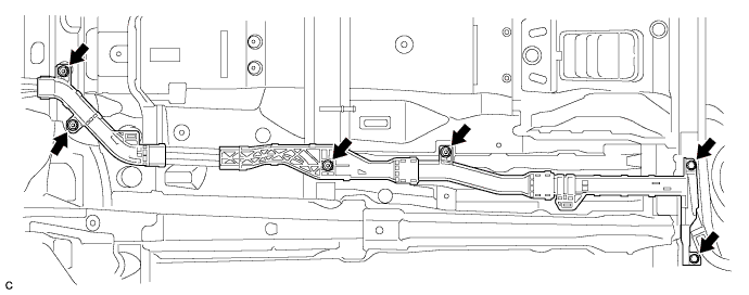
Disengage the 3 claws and push the frame wire out from the floor panel.
-
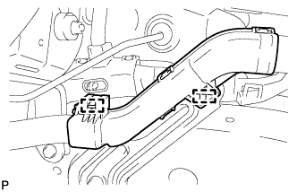
Disconnect the 2 wire harness clamps.
-
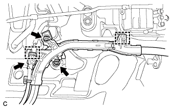
Disconnect the 2 wire harness clamps and connector.
-
Remove the 2 nuts.
-
Remove the 2 bolts.
-
Remove the 2 bolts and 4 nuts.
-
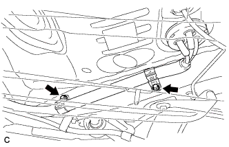
Disconnect the 2 clamps and remove the No. 4 floor wire.
Tech Tips
When removing the clamp, break the claw on the clamp. The clamp cannot be reused.
-