HV BATTERY REMOVAL

-
PRECAUTION
-
CHECK FOR DTCS
-
Check for DTCs Click here.
Note
Confirm that P0AA6 (Hybrid Battery Voltage System Isolation Fault) is not output before doing removal or installation work HV battery. If this DTC is output, perform troubleshooting for this DTC first.
-
-
REMOVE SERVICE PLUG GRIP
-
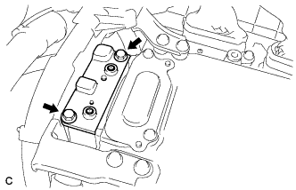
REMOVE CONNECTOR COVER ASSEMBLY
CAUTION:
-
Do not touch the high voltage connectors and terminals for 10 minutes after the service plug grip is removed.
-
Wear insulated gloves.
Note
Do not start the hybrid system with the service plug grip removed because it may cause a malfunction.
-
Remove the 2 bolts and connector cover assembly.
Note
-
Make sure to pull the connector cover assembly straight up, as a connector is connected to the bottom of the cover.
-
Do not allow any foreign objects or water to enter the inverter with converter assembly.
-
-
-
CHECK TERMINAL VOLTAGE
CAUTION:
Wear insulated gloves.
Note
Do not allow any foreign objects or water to enter the inverter with converter assembly.
-
Using a voltmeter, measure the voltage between the terminals of the 2 phase connectors.
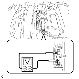
Standard voltage 0 V Tech Tips
Use a measuring range of DC 750 V or more on the voltmeter.
-
-
INSTALL CONNECTOR COVER ASSEMBLY
CAUTION:
Wear insulated gloves.
Note
-
Make sure that the interlock is fully engaged.
-
Do not allow any foreign objects or water to enter the inverter with converter assembly.
-
Install the connector cover assembly with the 2 bolts.
- Torque:
- 8.0 N*m { 82 kgf*cm, 71 in.*lbf }
-
-
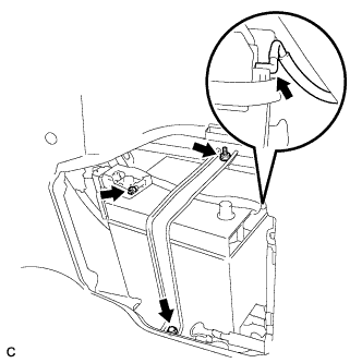
REMOVE AUXILIARY BATTERY
-
Open the auxiliary battery terminal cap.
-
Loosen the nut, and disconnect the positive (+) auxiliary battery cable.
-
Disconnect the auxiliary battery hose.
-
Loosen the nut, and remove the bolt.
-
Remove the auxiliary battery clamp.
-
Remove the auxiliary battery.
-
-
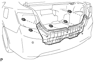
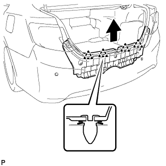
REMOVE REAR FLOOR FINISH PLATE
-
Remove the 5 clips.
-
Disengage the 4 clips and remove the rear floor finish plate.
-
-
REMOVE NO. 1 LUGGAGE COMPARTMENT TRIM HOOK
-
Push the 2 pins and remove the 2 No. 1 luggage compartment trim hooks.
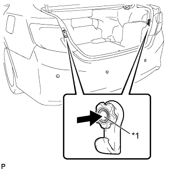
Text in Illustration *1 Pin
-
-
REMOVE LUGGAGE COMPARTMENT INNER TRIM COVER LH
-
Remove the clip <A>.
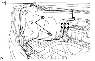
Text in Illustration *1 Clip <A> *2 Clip <B> -
Remove the 2 clips <B>.
-
Disengage the fastener and remove the luggage compartment inner trim cover LH.
-
-
REMOVE LUGGAGE COMPARTMENT INNER TRIM COVER RH
-
Remove the clip <A>.
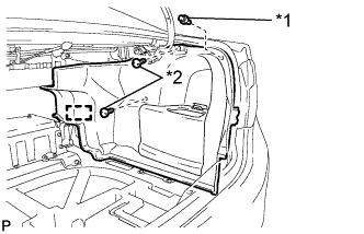
Text in Illustration *1 Clip <A> *2 Clip <B> -
Remove the 2 clips <B>.
-
Disengage the fastener and remove the luggage compartment inner trim cover RH.
-
-
REMOVE REAR SEAT CUSHION ASSEMBLY
-
Disengage the hook of the seat cushion from the vehicle body as shown in the illustration.
Note
Follow the instructions below carefully as the cushion frame can be deformed easily.
-
Choose a hook to disengage first. Place your hands near the hook as shown in the illustration. Then lift the seat cushion to disengage the hook.
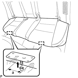
Standard Measurement a 100 mm (3.94 in.) or less -
Repeat the step above for the other hook.
-
-
Remove the rear seat cushion assembly.
-
-
REMOVE REAR SEAT CUSHION LOCK HOOK
-
Disengage the claw and remove the rear seat cushion lock hook.
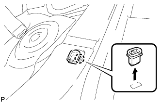
Note
Rear seat cushion lock hooks must not be reused.
Tech Tips
Use the same procedure for the RH side and the LH side.
-
-
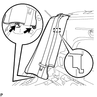
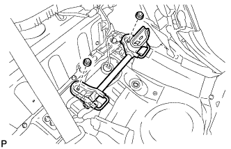
REMOVE REAR SEATBACK ASSEMBLY RH
-
Fold down the rear seatback assembly RH.
-
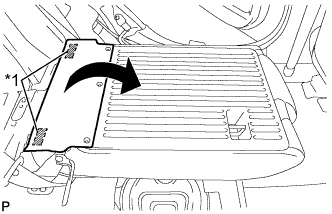
Disengage the 3 fasteners as shown in the illustration.
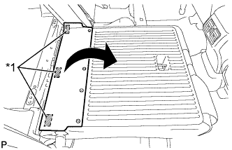
Text in Illustration *1 Fastener -
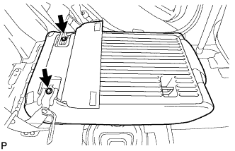
Remove the 2 bolts and rear seatback assembly RH.
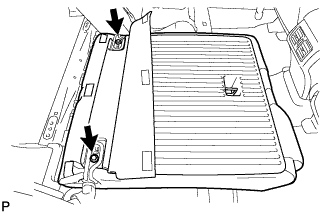
Note
Be careful not to damage the vehicle body.
-
-
REMOVE NO. 2 ROOM PARTITION COVER
-
Using a moulding remover, disengage the claw and guide, and remove the No. 2 room partition cover.
-
-
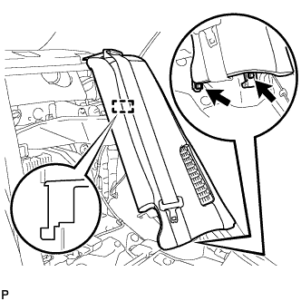
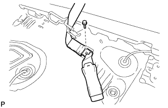
REMOVE REAR SEATBACK ASSEMBLY LH
-
Disconnect the rear seat inner with center belt assembly LH from the rear seat center shoulder belt guide.
-
Pull the cable in the direction shown in the illustration to release the rear seatback lock and then fold the rear seatback assembly LH forward.
-
Disengage the 2 fasteners as shown in the illustration.
Text in Illustration *1 Fastener -
Remove the 2 bolts and rear seatback assembly LH.
Note
Be careful not to damage the vehicle body.
-
-
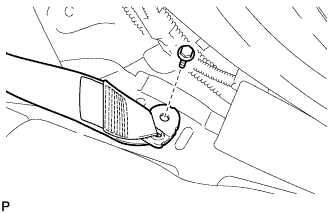
REMOVE REAR SIDE SEATBACK ASSEMBLY LH
-
Disconnect the rear seat outer belt from the rear seat shoulder belt guide LH.
-
Disconnect the connector.
-
Remove the 2 bolts.
-
Disengage the hook and remove the rear side seatback assembly LH.
-
-
REMOVE REAR SIDE SEATBACK ASSEMBLY RH
-
Disconnect the rear seat outer belt from the rear seat shoulder belt guide RH.
-
Disconnect the connector.
-
Remove the 2 bolts.
-
Disengage the hook and remove the rear side seatback assembly RH.
-
-
DISCONNECT REAR DOOR OPENING TRIM WEATHERSTRIP LH
-
Disconnect the rear door opening trim weatherstrip LH.
-
-
DISCONNECT REAR DOOR OPENING TRIM WEATHERSTRIP RH
-
Disconnect the rear door opening trim weatherstrip RH.
-
-
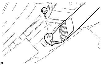
DISCONNECT REAR SEAT OUTER BELT ASSEMBLY (for LH Side)
-
Remove the bolt and disconnect the floor anchor of the rear seat outer belt assembly.
-
-
DISCONNECT REAR SEAT OUTER BELT ASSEMBLY (for RH Side)
-
Remove the bolt and disconnect the floor anchor of the rear seat outer belt assembly.
-
-
REMOVE CHILD RESTRAINT SEAT ANCHOR BRACKET SUB-ASSEMBLY LH
-
Remove the 2 nuts and child restraint seat anchor bracket sub-assembly LH.
-
-
DISCONNECT REAR SEAT INNER WITH CENTER BELT ASSEMBLY LH
-
Remove the bolt and disconnect the floor anchor of the rear seat inner with center belt assembly LH.
-
-
REMOVE ROOF SIDE INNER GARNISH LH
-
Disengage the 5 clips.
-
Disengage the guide and remove the roof side inner garnish LH.
-
-
REMOVE ROOF SIDE INNER GARNISH RH
Tech Tips
Use the same procedure as for the LH side.
-
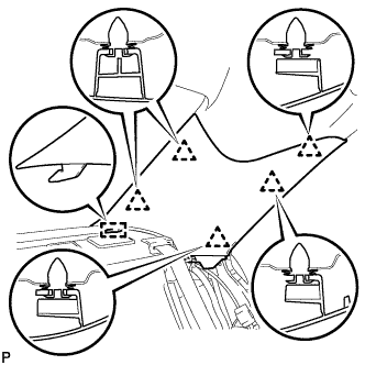
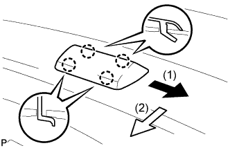
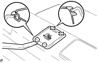
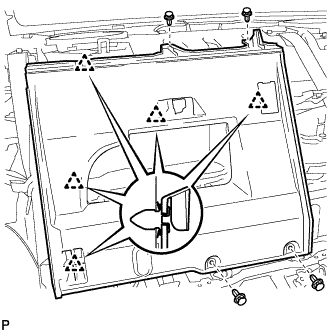
REMOVE CENTER STOP LIGHT SET
-
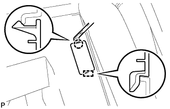
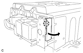
Slide the center stop light set in the order and directions shown by the arrows in the illustration while pushing it towards the rear of the vehicle to disengage the 4 claws.
-
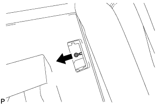
Turn the center stop light set 180 degrees as shown by the arrow in the illustration.
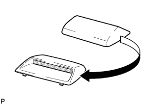
Tech Tips
This makes it easier to disconnect the connector.
-
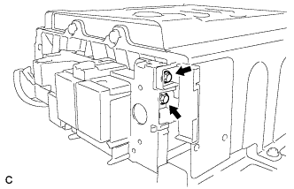
Disconnect the connector and remove the center stop light set.
-
-
REMOVE CHILD RESTRAINT SEAT TETHER ANCHOR COVER
-
Using a moulding remover, disengage the 2 claws and 2 guides to remove the child restraint seat tether anchor cover.
Tech Tips
Use the same procedure for the other 2 child restraint seat tether anchor covers.
-
-
REMOVE REAR SEAT SHOULDER BELT COVER
-
Using a moulding remover, disengage the 2 claws and 4 guides and remove the rear seat shoulder belt cover.
Tech Tips
Use the same procedure for the other 2 rear seat shoulder belt covers.
-
-
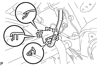
REMOVE PACKAGE TRAY TRIM PANEL ASSEMBLY
-
Using pliers, disengage the 3 clips from inside the luggage compartment as shown in the illustration.
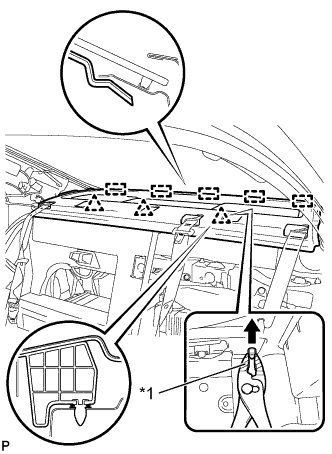
Text in Illustration *1 Protective Tape Tech Tips
Tape the tip of the pliers before use.
-
Disengage the 5 guides.
-
Pass the 3 rear seat belt floor anchors through the package tray trim panel assembly then remove the package tray trim panel assembly.
-
-
REMOVE NO. 1 ROOM PARTITION BOARD
-
Using a clip remover, remove the 4 clips.
-
Disengage the 5 clips and remove the No. 1 room partition board.
-
-
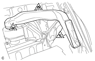
REMOVE NO. 1 HYBRID BATTERY INTAKE DUCT
-
Remove the 3 clips and No. 1 hybrid battery intake duct.
-
-
REMOVE NO. 4 HYBRID BATTERY SHIELD PANEL
CAUTION:
Wear insulated gloves.
-
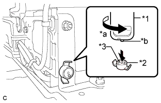
Using the service plug grip, remove the battery cover lock striker.
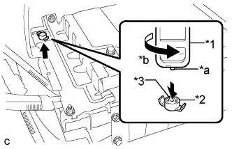
Text in Illustration *1 Service Plug Grip *2 Battery Cover Lock Striker *3 Button *a Projection *b Turn Tech Tips
Insert the projecting part of the service plug grip, and turn the button of the battery cover lock striker counterclockwise to release the lock.
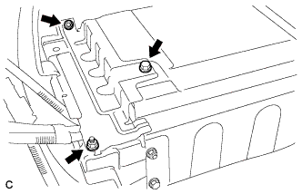
-
Remove the bolt, 2 nuts and No. 4 hybrid battery shield panel.
-
-
DISCONNECT NO. 4 FLOOR WIRE
CAUTION:
Wear insulated gloves.
Note
Insulate the disconnected connectors with insulating tape.
-
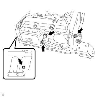
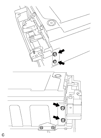
Disconnect the 2 connectors shown in the illustration.
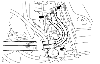
-
Disconnect the shielded wire ground and No. 4 floor wire.
-
-
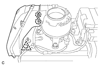
DISCONNECT LOW VOLTAGE CONNECTOR
-
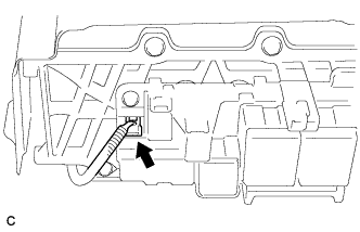
Disconnect the connector and clamp.
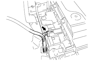
-
Disconnect the 2 connectors.
-
-
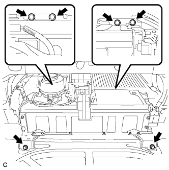
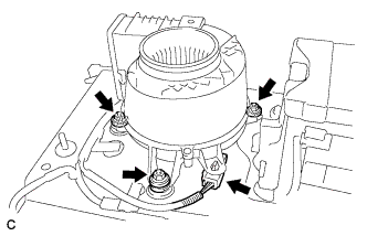
REMOVE HV BATTERY
CAUTION:
Wear insulated gloves.
-
Remove the 6 bolts from the HV battery.
-
Install the spare wheel cover assembly upside down.
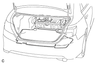
-
Cut and shape a piece of cardboard so that it fits the area between the HV battery bolt attachment positions, and then insert it as shown in the illustration.
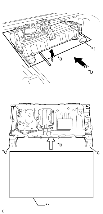
Text in Illustration *1 Cardboard *a Hold up *b Insert *c HV battery bolt attachment position -
Using a tire lever to hold up the HV battery, insert the cardboard until it cannot be inserted any further.
Note
Secure the No. 4 floor wire with electrical tape to prevent it from getting caught when moving the battery or other parts.
Tech Tips
Attach tape to the feet and edges of the battery to protect tools and the vehicle body.
-
Pull the cardboard and HV battery together to the middle of the luggage compartment.
Text in Illustration *1 Cardboard *a Pull Note
Use cardboard or other similar material to protect the HV battery and vehicle body from damage.
-
Remove the 2 nuts and No. 2 hybrid vehicle battery upper cover bracket.
-
Remove the clip.
-
Disengage the 2 claws and remove the No. 2 hybrid battery intake duct.
-
Disconnect the connector from the battery cooling blower assembly.
-
Remove the 3 nuts and battery cooling blower assembly.
Note
-
Be sure not to touch the fan part of the battery cooling blower assembly.
-
Do not lift the battery cooling blower assembly using the wire harness.
-
-
Remove the 2 clips.

-
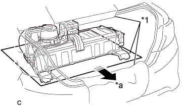
Turn the cardboard and HV battery 180° together.
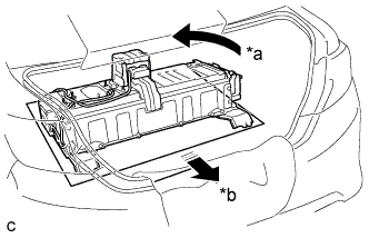
Text in Illustration *a Turn 180° *b Pull -
Pull the HV battery together with the cardboard toward the rear of the vehicle.
-
Using a suitable adaptor such as a rope, remove the HV battery while tilting it.
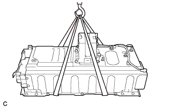
Note
While lowering the HV battery from the vehicle, do not allow it to contact the vehicle.
-
-
REMOVE NO. 2 HYBRID VEHICLE BATTERY SHIELD PANEL
CAUTION:
Wear insulated gloves.
-
Using the service plug grip, remove the battery cover lock striker.
Text in Illustration *1 Service Plug Grip *2 Battery Cover Lock Striker *3 Button *a Turn *b Projection Tech Tips
Insert the projection part of the service plug grip, and turn the button of the battery cover lock striker counterclockwise, and release the lock.
-
Disconnect the connector.
-
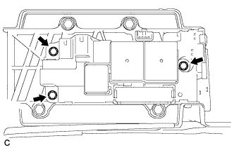
Remove the 2 bolts, nut and No. 2 hybrid vehicle battery shield panel.
-
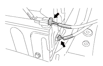
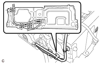
Disconnect the 3 wire harness clamps.
-
-
REMOVE BATTERY SMART UNIT
-
Disconnect the connector.
Note
Insulate the removed connector with insulating tape.
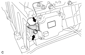
-
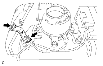
Remove the bolt and battery smart unit.
-
-
REMOVE NO. 1 HYBRID BATTERY SHIELD SUB-ASSEMBLY
CAUTION:
Wear insulated gloves.
-
Remove the bolt, 3 nuts and No. 1 hybrid battery shield sub-assembly.
-
-
REMOVE HYBRID BATTERY JUNCTION BLOCK ASSEMBLY
CAUTION:
Wear insulated gloves.
Note
Insulate the disconnected terminals with insulating tape.
-
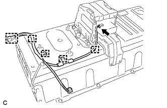
Disengage the claw and disconnect the terminal cover.
-
Using an insulated tool, remove the 2 bolts.
-
Disconnect the connector shown in the illustration.
-
Remove the 3 bolts and hybrid battery junction block assembly.
-
-
SEPARATE NO. 2 HYBRID BATTERY PACK WIRE
CAUTION:
Wear insulated gloves.
-
Disconnect the connector and 5 clamps, and remove the No. 2 hybrid battery pack wire.
-
-
REMOVE NO. 1 HYBRID VEHICLE BATTERY CARRIER BRACKET SUB-ASSEMBLY
-
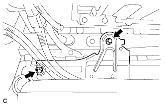
Remove the 2 bolts and No. 1 hybrid vehicle battery carrier bracket sub-assembly.
-
-
REMOVE NO. 2 HYBRID VEHICLE BATTERY CARRIER BRACKET SUB-ASSEMBLY
-
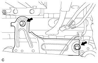
Remove the 2 bolts and No. 2 hybrid vehicle battery carrier bracket sub-assembly.
-