INVERTER WITH CONVERTER REMOVAL

-
PRECAUTION
-
REMOVE SERVICE PLUG GRIP
-
DRAIN COOLANT (for Inverter)
Note
-
Do not reuse the drained coolant because it may contain foreign objects.
-
Collect the drained coolant and measure its volume to establish a benchmark. When adding coolant, make sure to add more coolant than the measured amount.
-
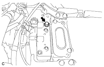
Remove the reserve tank cap.
CAUTION:
To avoid the danger of being burned, do not remove the reserve tank cap while the coolant for the inverter is still hot.
-
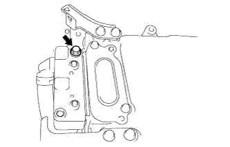
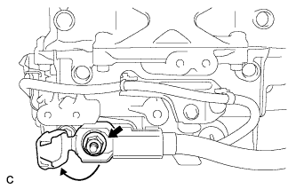
Using a hexagon wrench (10 mm), remove the drain plug indicated in the illustration and drain the coolant.
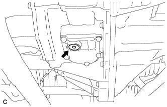
CAUTION:
Use caution when handling coolant immediately after driving or in summer because it may be hot.
-
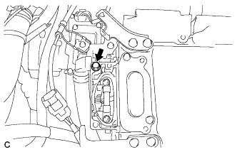
Install the plug with a new gasket.
- Torque:
- 39 N*m { 397 kgf*cm, 29 ft.*lbf }
-
-
REMOVE CONNECTOR COVER ASSEMBLY
CAUTION:
-
Do not touch the high voltage connectors and terminals for 10 minutes after the service plug grip is removed.
-
Wear insulated gloves.
Note
Do not start the hybrid system with the service plug grip removed because it may cause a malfunction.
-
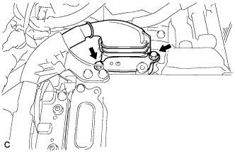
Remove the 2 bolts and connector cover assembly.
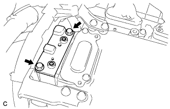
Note
-
Make sure to pull the connector cover assembly straight up, as a connector is connected to the bottom of the cover.
-
Do not allow any foreign objects or water to enter the inverter with converter assembly.
-
-
-
CHECK TERMINAL VOLTAGE
CAUTION:
Wear insulated gloves.
Note
Do not allow any foreign objects or water to enter the inverter with converter assembly.
-
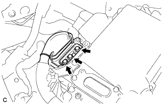
Using a voltmeter, measure the voltage between the terminals of the 2 phase connectors.
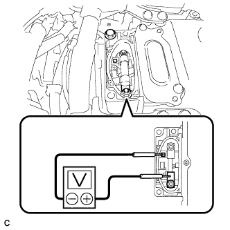
Standard voltage 0 V Tech Tips
Use a measuring range of DC 750 V or more on the voltmeter.
-
-
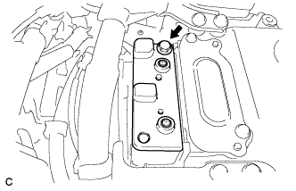
TEMPORARILY INSTALL CONNECTOR COVER ASSEMBLY
CAUTION:
Wear insulated gloves.
-
Temporarily install the connector cover assembly with the bolt to prevent any foreign objects or water from entering the inverter with converter assembly.
-
-
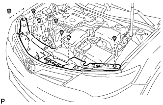
REMOVE COOL AIR INTAKE DUCT SEAL
-
Remove the 7 clips and cool air intake duct seal.
-
-
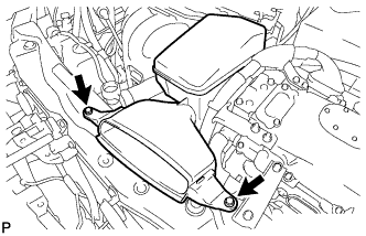
REMOVE INLET AIR CLEANER ASSEMBLY
-
Remove the 2 bolts and inlet air cleaner assembly.
-
-
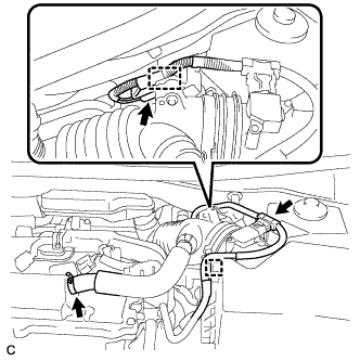
REMOVE AIR CLEANER CAP SUB-ASSEMBLY
-
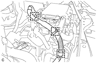
Disconnect the mass air flow meter connector and wire harness clamp from the air cleaner cap sub-assembly.
-
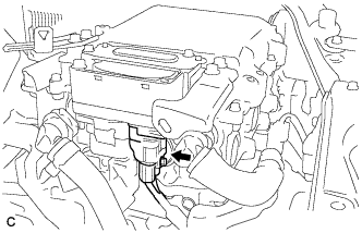
Disconnect the ventilation hose from the cylinder head cover.
-
Disconnect the connector and wire harness clamp.
-
Release the 2 clamps and remove the air cleaner cap sub-assembly.
-
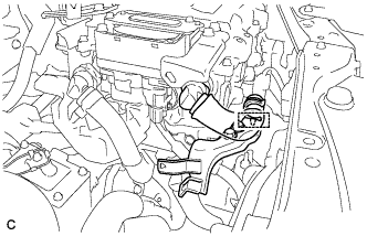
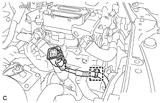
Disconnect the 2 fuel vapor feed hoses.
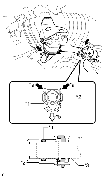
Text in Illustration *1 Retainer *2 Fuel Tube Connector *3 Pipe *4 O-ring *a Pinch *b Pull Note
-
Remove any dirt or foreign matter on the fuel tube connector before performing this work.
-
Do not allow any scratches or foreign matter to get on the parts when disconnecting them as the fuel tube connector has an O-ring that seals the pipe.
-
Perform this work by hand. Do not use any tools.
-
Protect the disconnected parts by covering them with plastic bags after disconnecting each fuel vapor feed hose.
-
-
Loosen the hose clamp and disconnect the air cleaner hose from the throttle with motor body assembly.
-
-
REMOVE AIR CLEANER FILTER ELEMENT SUB-ASSEMBLY
-
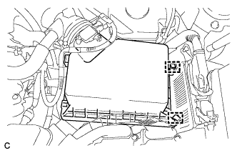
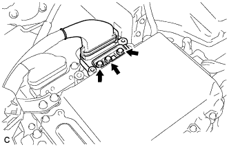
REMOVE AIR CLEANER CASE SUB-ASSEMBLY
-
Remove the 2 bolts and air cleaner case sub-assembly.
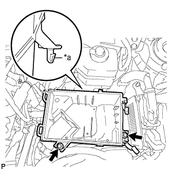
Text in Illustration *a Projection
-
-
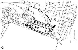
REMOVE NO. 5 INVERTER BRACKET
-
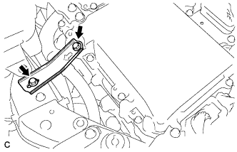
Remove the 2 bolts and No. 5 inverter bracket.
-
-
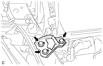
REMOVE NO. 4 INVERTER BRACKET
-
Remove the 3 bolts and No. 4 inverter bracket.
-
-
REMOVE UPPER INVERTER COVER
CAUTION:
Wear insulated gloves.
-
Remove the 2 bolts and upper inverter cover (generator cable side).
Note
-
Make sure to pull the upper inverter cover straight up, as a connector is connected to the bottom of the cover.
-
Do not touch the upper inverter cover waterproofing rubber.
-
-
-
DISCONNECT GENERATOR CABLE
CAUTION:
Wear insulated gloves.
-
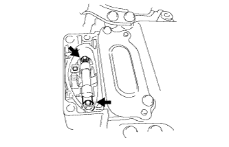
Using an insulated tool, remove the 3 bolts.
-
Disconnect the 2 wire harness clamps and separate the generator cable.
Note
-
Do not damage the terminals, connector housings or inverter with converter assembly when disconnecting them.
-
Do not touch the connector waterproofing rubber or terminals.
-
Insulate the removed terminals with insulating tape.
-
Do not allow any foreign objects or water to enter the inverter with converter assembly.
-
-
-
REMOVE UPPER INVERTER COVER
CAUTION:
Wear insulated gloves.
-
Remove the 2 bolts and upper inverter cover (motor cable side).
Note
-
Make sure to pull the upper inverter cover straight up, as a connector is connected to the bottom of the cover.
-
Do not touch the upper inverter cover waterproofing rubber.
-
-
-
DISCONNECT MOTOR CABLE
CAUTION:
Wear insulated gloves.
-
Using an insulated tool, remove the 3 bolts.
-
Disconnect the 3 wire harness clamps and separate the motor cable.
Note
-
Do not damage the terminals, connector housings or inverter with converter assembly when disconnecting them.
-
Do not touch the connector waterproofing rubber or terminals.
-
Insulate the removed terminals with insulating tape.
-
Do not allow any foreign objects or water to enter the inverter with converter assembly.
-
-
-
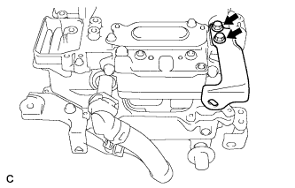
REMOVE NO. 3 MOTOR CABLE BRACKET
-
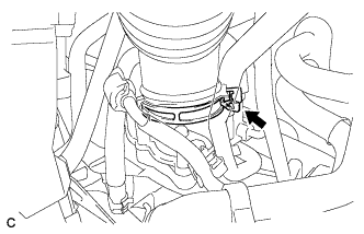
Disconnect the hose clamp from the No. 3 motor cable bracket.
Tech Tips
Do not remove the hose clamp from the hose.
-
Remove the 2 bolts and No. 3 motor cable bracket.
-
-
REMOVE CONNECTOR COVER ASSEMBLY
CAUTION:
Wear insulated gloves.
-
Remove the bolt and connector cover assembly.
Note
-
Make sure to pull the connector cover assembly straight up, as a connector is connected to the bottom of the cover.
-
Do not allow any foreign objects or water to enter the inverter with converter assembly.
-
-
-
DISCONNECT NO. 4 ENGINE WIRE
CAUTION:
Wear insulated gloves.
-
Disconnect the No. 4 engine wire.
Note
-
Do not damage the terminals, connector housings or inverter with converter assembly when disconnecting them.
-
Do not touch the connector waterproofing rubber or terminals.
-
Insulate the removed terminals with insulating tape.
-
Do not allow any foreign objects or water to enter the inverter with converter assembly.
-
-
Disconnect the wire harness clamp.
-
-
DISCONNECT NO. 4 FLOOR WIRE
CAUTION:
Wear insulated gloves.
-
Remove the bolt.
-
Disconnect the wire harness clamp and connector.
Note
-
Do not damage the terminals, connector housings or inverter with converter assembly when disconnecting them.
-
Do not touch the connector waterproofing rubber or terminals.
-
Insulate the removed terminals with insulating tape.
-
Do not allow any foreign objects or water to enter the inverter with converter assembly.
-
-
-
TEMPORARILY INSTALL CONNECTOR COVER ASSEMBLY
CAUTION:
Wear insulated gloves.
-
Temporarily install the connector cover assembly with the bolt to prevent any foreign objects or water from entering the inverter with converter assembly.
-
-
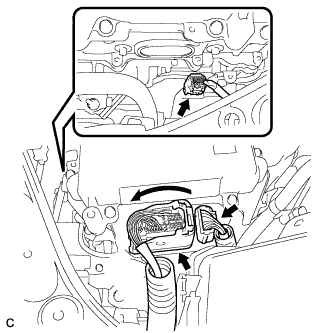
DISCONNECT LOW VOLTAGE CONNECTOR
Note
-
Insulate the removed terminals with insulating tape.
-
Do not allow any foreign objects or water to enter the inverter with converter assembly.
-
Raise the lock lever and disconnect the 3 low voltage connectors.
-
Disconnect the low voltage connector from the inverter with converter assembly.
-
-
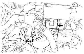
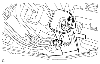
DISCONNECT NO. 3 ENGINE ROOM WIRE
-
Remove the relay block cover.
-
Remove the nut.
-
Disconnect the wire harness clamp and No. 3 engine room wire.
-
-
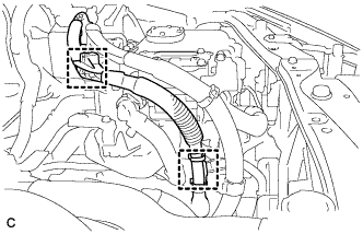
REMOVE NO. 4 INVERTER COOLING HOSE
-
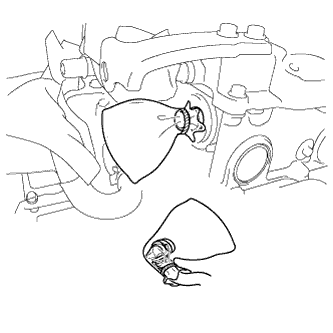
Release the retainer and disconnect the No. 4 inverter cooling hose from the inverter with converter assembly.
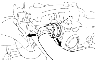
Text in Illustration *1 Retainer -
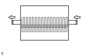
Put pieces of cloth into the pipes and in the disconnected hoses, or cover the pipes and hoses with plastic bags as shown in the illustration to prevent foreign matter from entering the cooling system and to prevent coolant from spilling near the inverter with converter assembly.
-
-
REMOVE NO. 1 INVERTER COOLING HOSE ASSEMBLY
-
Release the retainer and disconnect the No. 1 inverter cooling hose from the inverter with converter assembly.
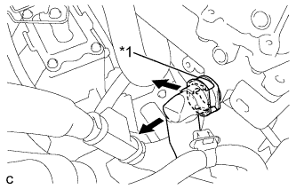
Text in Illustration *1 Retainer -
Put pieces of cloth into the pipes and in the disconnected hoses, or cover the pipes and hoses with plastic bags as shown in the illustration to prevent foreign matter from entering the cooling system and to prevent coolant from spilling near the inverter with converter assembly.
-
-
REMOVE INVERTER WITH CONVERTER ASSEMBLY
CAUTION:
Wear insulated gloves.
-
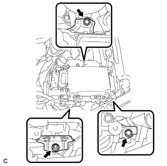
Temporarily secure the No. 3 engine room wire with the inverter with converter assembly hook as shown in the illustration.
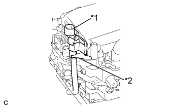
Text in Illustration *1 No. 3 Engine Room Wire *2 Hook -
Remove the 2 bolts, nut and inverter with converter assembly.
Note
-
Since the inverter with converter assembly is very heavy, 2 people are needed to remove the inverter with converter assembly. When removing the inverter with converter assembly, do not damage the parts around it.
-
To prevent damage, do not hold the inverter with converter assembly by the connectors.
-
To prevent damage due to static electricity, do not touch the terminals of the disconnected connectors.
-
-
Even after the coolant is drained, coolant remains in the inverter with converter assembly due to its internal structure. Therefore, seal or cover the pipes when removing the inverter with converter to prevent coolant from spilling out or foreign matter from entering the inverter with converter.
-
-
REMOVE HIGH VOLTAGE FUSE
CAUTION:
Wear insulated gloves.
Tech Tips
Perform this procedure only when replacement of the high voltage fuse is necessary.
-
Remove the bolt and connector cover assembly.
Note
-
Make sure to pull the connector cover assembly straight up, as a connector is connected to the bottom of the cover.
-
Do not allow any foreign objects or water to enter the inverter with converter assembly.
-
-
Remove the 2 nuts and high voltage fuse.
-
Temporarily install the connector cover assembly with the bolt to prevent any foreign objects or water from entering the inverter with converter assembly.
-
-
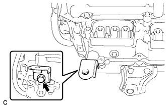
REMOVE AIR CLEANER BRACKET
-
Remove the bolt and air cleaner bracket.
-
-
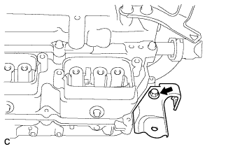
REMOVE AIR CLEANER BRACKET
-
Remove the bolt and air cleaner bracket.
-
-
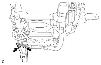
REMOVE NO. 1 INVERTER BRACKET
-
Remove the 2 bolts and No. 1 inverter bracket.
-
-
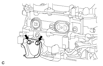
REMOVE NO. 2 INVERTER BRACKET
-
Remove the 2 bolts and No. 2 inverter bracket.
-
-
REMOVE NO. 3 INVERTER BRACKET
-
Remove the 2 bolts and No. 3 inverter bracket.
-
-
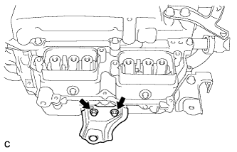
REMOVE NO. 1 MOTOR CABLE BRACKET
-
Remove the 2 bolts and No. 1 motor cable bracket.
-
-
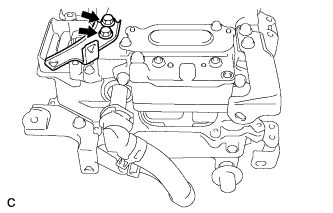
REMOVE NO. 2 MOTOR CABLE BRACKET
-
Remove the 2 bolts and No. 2 motor cable bracket.
-
-
REMOVE NO. 1 INVERTER COOLING HOSE
-
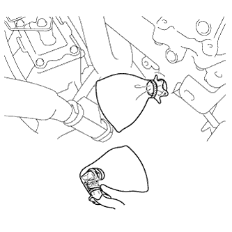
Release the retainer and disconnect the No. 1 inverter cooling hose from the inverter with converter assembly.
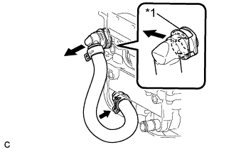
Text in Illustration *1 Retainer -
Remove the No. 1 inverter cooling hose.
-
Put pieces of cloth into the pipes and in the disconnected hoses, or cover the pipes and hoses with plastic bags as shown in the illustration to prevent foreign matter from entering the cooling system and to prevent coolant from spilling near the inverter with converter assembly.
-
-
REMOVE NO. 3 ENGINE ROOM WIRE
-
Open the cover.
Note
Do not twist the cover excessively when opening it.
-
Remove the nut and No. 3 engine room wire.
-