ENGINE ASSEMBLY INSTALLATION

Tech Tips
Perform "Inspection After Repair" after replacing the engine assembly Click here.
-
REMOVE ENGINE STAND
-
Using a chain block and engine sling device, secure the engine assembly.
Note
-
Adjust the angle of the sling device carefully to prevent the engine assembly or engine hanger from deforming or becoming damaged.
-
Servicing an engine assembly while it is hanging is dangerous. This can be done only when installing/removing the engine assembly to/from an engine stand.
-
-
Remove the engine stand from the engine.
-
-
INSTALL ENGINE WIRE
-
Install the engine wire to the engine with transaxle.
-
-
INSTALL FLYWHEEL SUB-ASSEMBLY
-
Using SST, hold the crankshaft.
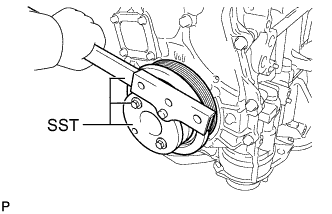
- SST
- 09213-54015
- 91551-80650
- 09330-00021
-
Apply a few drops of adhesive to 2 or 3 threads at the tip of each of the 8 bolts.
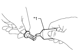
Text in Illustration *1 Adhesive Adhesive Toyota Genuine Adhesive 1324, Three Bond 1324 or equivalent -
Install and uniformly tighten the 8 bolts in the sequence shown in the illustration.
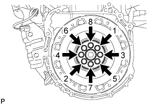
- Torque:
- 130 N*m { 1326 kgf*cm, 96 ft.*lbf }
Note
Do not start the engine for at least an hour after installing the flywheel sub-assembly.
-
Check that the crankshaft turns smoothly.
-
-
INSTALL TRANSMISSION INPUT DAMPER ASSEMBLY
-
Using SST, hold the crankshaft.
- SST
- 09213-54015
- 09330-00021
- 91551-80650
-
Install the transmission input damper assembly.
-
Install and uniformly tighten the 6 bolts in the sequence shown in the illustration.
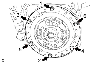
- Torque:
- 30 N*m { 306 kgf*cm, 22 ft.*lbf }
Note
-
Take care not to insert the transmission input damper assembly in the wrong direction.
-
-
INSTALL HYBRID VEHICLE TRANSAXLE ASSEMBLY
-
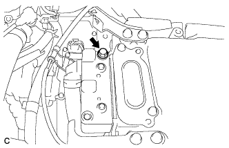
Make sure that the knock pins are installed to the engine.
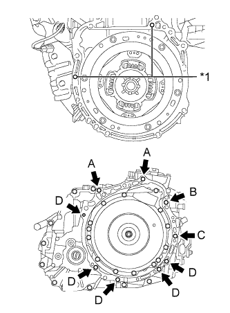
Text in Illustration *1 Knock Pin -
Install the hybrid vehicle transaxle assembly to the engine with the 9 bolts.
Bolt Bolt Length Torque A, B 55 mm (2.17 in.) 64 N*m (653 kgf*cm, 47 ft.*lbf) C 65 mm (2.56 in.) 46 N*m (469 kgf*cm, 34 ft.*lbf) D 32 mm (1.26 in.) 44 N*m (449 kgf*cm, 32 ft.*lbf) E 38 mm (1.50 in.) 28 N*m (286 kgf*cm, 21 ft.*lbf) Note
-
Do not apply grease either to the spline or to the input shaft.
-
Make sure that the wire harness or similar items are not pinched between the contact surfaces.
-
Do not forcibly pry on the hybrid vehicle transaxle.
-
Make sure to align the hybrid vehicle transaxle so that the input shaft of the hybrid vehicle transaxle will be inserted straight into the inner splines of the transmission input damper.
-
When inserting the input shaft of the hybrid vehicle transaxle into the inner splines of the transmission input damper, do not shake the hybrid vehicle transaxle excessively.
-
When mounting the hybrid vehicle transaxle to the engine, make sure to securely fit the knock pins into the knock holes.
Tech Tips
Temporarily tighten bolt B first.
-
-
-
INSTALL ENGINE MOUNTING BRACKET RH
-
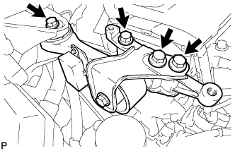
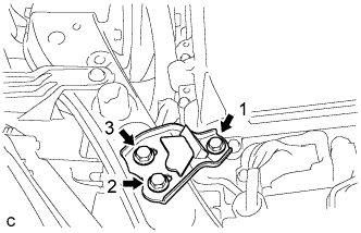
Install the engine mounting bracket RH with the 3 bolts.
- Torque:
- 54 N*m { 551 kgf*cm, 40 ft.*lbf }
-
-
INSTALL DRIVE SHAFT BEARING BRACKET
-
Install the drive shaft bearing bracket with the 3 bolts.
- Torque:
- 64 N*m { 653 kgf*cm, 47 ft.*lbf }
-
-
TEMPORARILY INSTALL FRONT ENGINE MOUNTING INSULATOR
-
Temporarily install the front engine mounting insulator with the 3 nuts.
Tech Tips
Perform this procedure only when replacement of the front engine mounting insulator is necessary.
-
-
TEMPORARILY INSTALL ENGINE MOUNTING INSULATOR LH
-
Temporarily install the engine mounting insulator LH with the 3 nuts.
Tech Tips
Perform this procedure only when replacement of the engine mounting insulator LH is necessary.
-
-
TEMPORARILY INSTALL ENGINE MOUNTING INSULATOR RH
-
Temporarily install the engine mounting insulator RH with the 3 nuts.
Tech Tips
Perform this procedure only when replacement of the engine mounting insulator RH is necessary.
-
-
INSTALL FRONT FRAME ASSEMBLY
-
Install the engine mounting insulator LH with the nut.
- Torque:
- 95 N*m { 969 kgf*cm, 70 ft.*lbf }
-
Install the engine mounting insulator RH with the nut.
- Torque:
- 95 N*m { 969 kgf*cm, 70 ft.*lbf }
-
Install the front engine mounting insulator with the bolt.
- Torque:
- 87 N*m { 887 kgf*cm, 64 ft.*lbf }
-
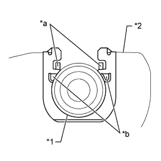
Fully tighten the 9 temporarily installed nuts of the engine mounting insulators to the specified torque.
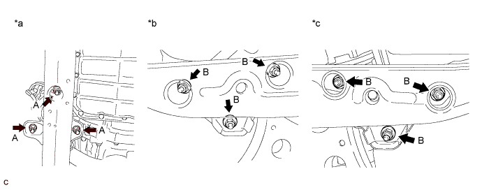
Text in Illustration *a Front Engine Mounting Insulator *b Engine Mounting Insulator RH *c Engine Mounting Insulator LH - - Tech Tips
Perform this procedure only when replacement of the engine mounting insulator is necessary.
- Torque:
- A
- 52 N*m { 530 kgf*cm, 38 ft.*lbf }
- B
- 87 N*m { 887 kgf*cm, 64 ft.*lbf }
-
Install the 4 hole plugs.
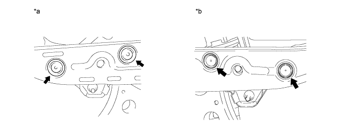
Text in Illustration *a Engine Mounting Insulator RH *b Engine Mounting Insulator LH Tech Tips
Perform this procedure only when replacement of the engine mounting insulator is necessary.
-
-
INSTALL FRONT DRIVE SHAFT HOLE SNAP RING LH
-
Install a new front drive shaft hole snap ring LH.
Note
Face the end gap of the front drive shaft hole snap ring downward.
-
-
INSTALL FRONT DRIVE SHAFT ASSEMBLY LH
-
Coat the spline of the front drive inboard joint assembly with ATF.
-
Coat the lip of the hybrid vehicle transaxle assembly type T oil seal with MP grease.
-
Align the inboard joint splines, and using a brass bar and a hammer, install the front drive shaft assembly LH.
Note
-
Face the end gap of the front drive shaft hole snap ring LH downward.
-
Do not damage the hybrid vehicle transaxle assembly type T oil seal.
-
Do not damage the front axle inboard joint boot.
-
Make sure to center the front drive shaft assembly LH during installation to prevent damage to the front drive shaft hole snap ring LH.
Tech Tips
Confirm whether the drive shaft is securely driven in by checking the reaction force and sound.
-
-
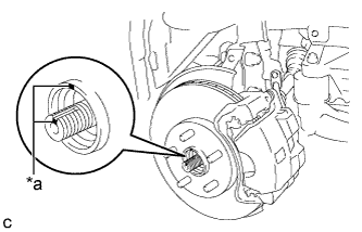
Apply mineral oil base grease to the areas indicated by the arrows in the illustration on the front drive shaft assembly LH contact surface of the front axle hub bearing.
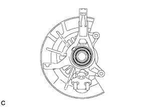
Text in Illustration 
Mineral Oil Base Grease Tech Tips
Apply 0.1 to 0.3 g (0.00353 to 0.0106 oz.) of mineral oil base grease to each area.
-
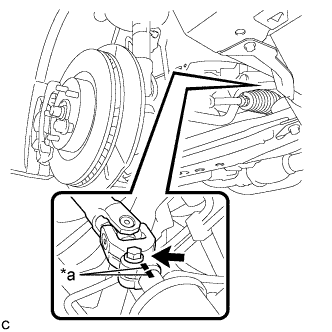
Align the matchmarks and install the front drive shaft assembly LH to the front axle hub sub-assembly.
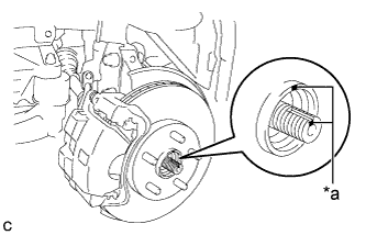
Text in Illustration *a Matchmark Note
Be careful not to damage the front axle outboard joint boot or speed sensor rotor.
-
-
INSTALL FRONT DRIVE SHAFT ASSEMBLY RH
-
Coat the spline of the front drive inboard joint assembly with ATF.
-
Coat the lip of the hybrid vehicle transaxle assembly type T oil seal with MP grease.
-
Install a new bearing bracket hole snap ring to the front drive shaft assembly RH.
-
Install the front drive shaft assembly RH.
Note
-
Do not damage the hybrid vehicle transaxle assembly type T oil seal.
-
Do not damage the front axle inboard joint boot.
-
When inserting the front drive shaft assembly RH, keep it level.
-
-
Install the bearing bracket hole snap ring and a new bolt.
- Torque:
- 32 N*m { 330 kgf*cm, 24 ft.*lbf }
-
Apply mineral oil base grease to the areas indicated by the arrows in the illustration on the front drive shaft assembly RH contact surface of the front axle hub bearing.
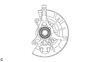
Text in Illustration Mineral Oil Base Grease Tech Tips
Apply 0.1 to 0.3 g (0.00353 to 0.0106 oz.) of mineral oil base grease to each area.
-
Align the matchmarks and install the front drive shaft assembly RH to the front axle hub sub-assembly.
Text in Illustration *a Matchmark Note
Be careful not to damage the front axle outboard joint boot or speed sensor rotor.
-
-
INSTALL ENGINE ASSEMBLY WITH TRANSAXLE
-
Set the engine assembly with transaxle on an engine lifter.
Note
-
Install a height adjustment attachment and plate lift attachment onto the engine assembly with transaxle.
-
Do not position a height adjustment attachment or plate lift attachment onto the front frame assembly.
-
To prevent the oil pan from deforming, do not place any attachments onto the oil pan of the engine assembly with transaxle.
-
Make sure to support the engine assembly with transaxle securely to prevent it from falling.
-
-
Remove the engine hangers Click here.
-
Install the engine assembly to the vehicle.
Note
Do not raise the engine more than necessary. If the engine is raised excessively, the vehicle may also be lifted up.
Tech Tips
-
Make sure that the engine is clear of all wiring and hoses.
-
While raising the engine into the vehicle, do not allow it to contact the vehicle.
-
-
Install the frame side rail plate RH and LH with the 4 bolts and 2 nuts.
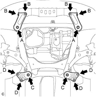
- Torque:
- A
- 85 N*m { 867 kgf*cm, 62 ft.*lbf }
- B
- 32 N*m { 326 kgf*cm, 24 ft.*lbf }
-
Install the front suspension member brace rear RH and LH with the 4 bolts and 2 nuts.
- Torque:
- C
- 85 N*m { 867 kgf*cm, 62 ft.*lbf }
- D
- 32 N*m { 326 kgf*cm, 24 ft.*lbf }
Tech Tips
Perform "Inspection After Repair" after replacing the engine assembly Click here.
-
-
INSTALL FLYWHEEL HOUSING UNDER COVER
-
Install the flywheel housing under cover.
-
-
INSTALL FRONT LOWER NO. 1 SUSPENSION ARM SUB-ASSEMBLY LH
-
Connect the front lower No. 1 suspension arm sub-assembly to the front lower ball joint assembly with the bolt and 2 nuts.
- Torque:
- 75 N*m { 765 kgf*cm, 55 ft.*lbf }
-
-
INSTALL FRONT LOWER NO. 1 SUSPENSION ARM SUB-ASSEMBLY RH
Tech Tips
Use the same procedure described for the LH side.
-
INSTALL TIE ROD ASSEMBLY LH
-
Connect the tie rod assembly LH to the steering knuckle with the nut.
- Torque:
- 49 N*m { 500 kgf*cm, 36 ft.*lbf }
-
Install a new cotter pin.
Note
Further tighten the nut up to 60° if the holes for the cotter pin are not aligned.
-
-
INSTALL TIE ROD ASSEMBLY RH
Tech Tips
Use the same procedure described for the LH side.
-
INSTALL FRONT SPEED SENSOR LH
-
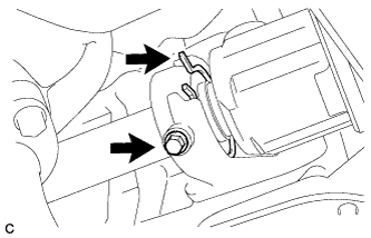
Install the front speed sensor and front flexible hose to the front shock absorber with the bolt and clamp.
- Torque:
- 19 N*m { 192 kgf*cm, 14 ft.*lbf }
Note
Do not twist the front speed sensor when installing it.
Tech Tips
Install the speed sensor harness bracket first and then the front flexible hose.
-
Install the front speed sensor to the steering knuckle with the bolt.
- Torque:
- 8.5 N*m { 87 kgf*cm, 75 in.*lbf }
Note
Do not twist the front speed sensor when installing it.
-
-
INSTALL FRONT SPEED SENSOR RH
Tech Tips
Use the same procedure described for the LH side.
-
INSTALL FRONT STABILIZER LINK ASSEMBLY LH
-
Install the front stabilizer link assembly to the front shock absorber assembly with the nut.
- Torque:
- 125 N*m { 1275 kgf*cm, 92 ft.*lbf }
If the ball joint turns together with the nut, use a wrench to hold the stud bolt.
-
-
INSTALL FRONT STABILIZER LINK ASSEMBLY RH
Tech Tips
Use the same procedure described for the LH side.
-
INSTALL FRONT AXLE SHAFT NUT LH
-
Clean the threaded parts on the front drive shaft assembly and a new axle shaft nut using a non-residue solvent.
Note
-
Be sure to perform this work even when using a new drive shaft.
-
Keep the threaded parts free of oil and foreign matter.
-
-
Using a socket wrench (30 mm), install the front axle shaft nut.
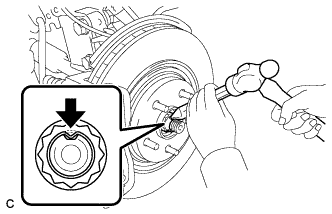
- Torque:
- 294 N*m { 2998 kgf*cm, 217 ft.*lbf }
-
Using a chisel and a hammer, stake the front axle shaft nut.
-
-
CONNECT STEERING INTERMEDIATE SHAFT ASSEMBLY
-
Align the matchmarks and install the steering intermediate shaft to the steering link assembly.
Text in Illustration *a Matchmark -
Install the bolt.
- Torque:
- 35 N*m { 360 kgf*cm, 26 ft.*lbf }
-
-
INSTALL FRONT AXLE SHAFT NUT RH
Tech Tips
Use the same procedure described for the LH side.
-
INSTALL FRONT EXHAUST PIPE ASSEMBLY
-
Using a vernier caliper, measure the free length of the compression spring.
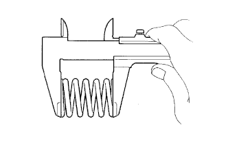
Standard 42.0 mm (1.65 in.) Minimum 40.5 mm (1.60 in.) Tech Tips
If the length is less than the minimum, replace the compression spring.
-
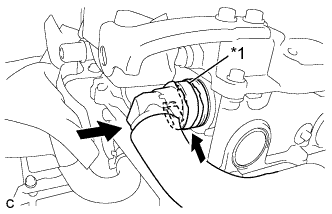
Fully insert a new gasket to the exhaust manifold converter sub-assembly.
-
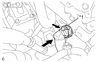
Using a plastic hammer and wooden block, tap in the new gasket until its surface is flush with the exhaust manifold converter sub-assembly.
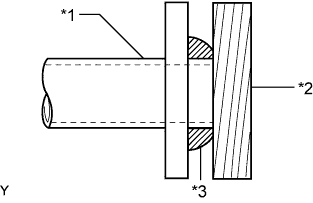
Text in Illustration *1 Exhaust Manifold Converter Sub-assembly *2 Wooden Block *3 Gasket Note
-
Be sure to install the gasket in the correct direction.
-
Do not reuse the gasket.
-
Do not damage the gasket.
-
Do not push in the gasket by using the exhaust pipe when connecting it.
-
-
Connect the front exhaust pipe assembly to the exhaust pipe support.
-
Install the front exhaust pipe assembly with the 2 compression springs and 2 bolts.
- Torque:
- 43 N*m { 438 kgf*cm, 32 ft.*lbf }
Tech Tips
After the installation, check that the gaps between the flanges of the exhaust manifold converter sub-assembly and front exhaust pipe assembly are consistent front-to-rear and left-to-right.
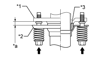
Text in Illustration *1 Exhaust Manifold Converter Sub-assembly *2 Front Exhaust Pipe Assembly *3 Gasket *a Space between flanges: 8.5 mm (0.335 in.)
-
-
CONNECT NO. 1 COOLER REFRIGERANT DISCHARGE HOSE
-
Remove the vinyl tape from the hose.
-
Sufficiently apply compressor oil to a new O-ring and the fitting surface of the compressor with motor assembly.
Compressor oil ND-OIL 11 or equivalent -
Install the O-ring to the No. 1 cooler refrigerant discharge hose.
Note
-
Keep the O-ring and O-ring fitting surfaces free from dirt or any foreign objects.
-
Do not use any compressor oil other than ND-OIL 11 or equivalent. If any compressor oil other than ND-OIL 11 or equivalent is used, compressor motor insulation performance may decrease, resulting in a leakage of electric power.
-
-
Install the No. 1 cooler refrigerant discharge hose to the compressor with motor assembly with the bolt.
- Torque:
- 9.8 N*m { 100 kgf*cm, 87 in.*lbf }
-
-
CONNECT SUCTION HOSE SUB-ASSEMBLY
-
Remove the vinyl tape from the hose.
-
Sufficiently apply compressor oil to a new O-ring and the fitting surface of the compressor with motor assembly.
Compressor oil ND-OIL 11 or equivalent -
Install the O-ring to the suction hose sub-assembly.
Note
-
Keep the O-ring and O-ring fitting surfaces free from dirt or any foreign objects.
-
Do not use any compressor oil other than ND-OIL 11 or equivalent. If any compressor oil other than ND-OIL 11 or equivalent is used, compressor motor insulation performance may decrease, resulting in a leakage of electric power.
-
-
Install the suction hose sub-assembly to the compressor with motor assembly with the bolt.
- Torque:
- 9.8 N*m { 100 kgf*cm, 87 in.*lbf }
-
-
INSTALL ENGINE MOVING CONTROL ROD
-
Temporarily install the engine moving control rod to the engine moving control rod bracket with the bolt.
Tech Tips
Perform this procedure only when replacement of the engine moving control rod is necessary.
-
-
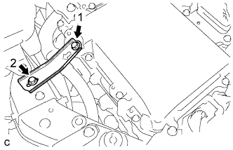
INSTALL ENGINE MOVING CONTROL ROD SUB-ASSEMBLY
-
When the engine moving control rod has been replaced.
-
Temporarily install the engine moving control rod sub-assembly with the 4 bolts.
-
Fully tighten the engine moving control rod sub-assembly with the bolts except bolt A.
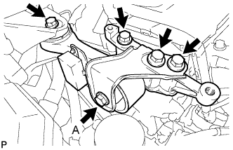
- Torque:
- 38 N*m { 387 kgf*cm, 28 ft.*lbf }
-
Using SST, fully tighten the bolt A.
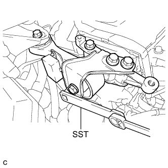
- SST
- 09961-00950
- Torque:
- without SST
- 52 N*m { 530 kgf*cm, 38 ft.*lbf }
- with SST
- 33 N*m { 340 kgf*cm, 25 ft.*lbf }
Note
-
The "with SST" torque value is effective when using SST with a fulcrum length of 150 mm (5.91 in.) and a torque wrench with a fulcrum length of 260 mm (10.24 in.) Click here.
-
The "with SST" torque value is effective when SST is parallel to the torque wrench.
-
Fully tighten bolt A using SST.
-
-
When the engine moving control rod has been reused.
-
Temporarily install the engine moving control rod sub-assembly with the 4 bolts.
-
Fully tighten the engine moving control rod sub-assembly with the 4 bolts.
- Torque:
- 38 N*m { 387 kgf*cm, 28 ft.*lbf }
-
-
-
INSTALL EARTH WIRE
-
Install the earth wire with the bolt.
- Torque:
- 8.0 N*m { 82 kgf*cm, 71 in.*lbf }
-
-
INSTALL NO. 2 ENGINE MOUNTING STAY RH
-
Install the No. 2 engine mounting stay RH with the 2 bolts.
- Torque:
- 38 N*m { 387 kgf*cm, 28 ft.*lbf }
-
-
CONNECT FUEL MAIN TUBE
-
Push in the fuel tube connector to the fuel pipe until the connector makes a "click" sound.
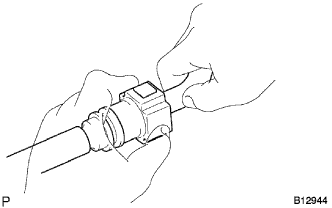
Note
-
Check for damage or contamination on the connected part of the pipe.
-
Check if the pipe and the connector are securely connected by trying to pull them apart.
-
-
Install the No. 1 fuel pipe clamp.
-
-
CONNECT INLET HEATER WATER HOSE
-
Connect the inlet heater water hose.
-
-
CONNECT OUTLET HEATER WATER HOSE
-
Connect the outlet heater water hose.
-
-
CONNECT NO. 5 INVERTER COOLING HOSE
-
Connect the No. 5 inverter cooling hose to the hybrid vehicle transaxle assembly.
-
-
CONNECT NO. 1 RADIATOR HOSE
-
Connect the air fuel ratio sensor wire to the No. 1 radiator hose with the hose clamp.
-
-
CONNECT NO. 2 RADIATOR HOSE
-
Connect the No. 2 radiator hose.
-
-
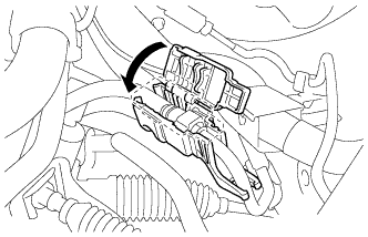
CONNECT TRANSMISSION CONTROL CABLE ASSEMBLY
-
Connect the transmission control cable assembly to the 2 transmission control cable brackets.
-
Install a new clip to the No. 1 transmission control cable bracket.
-
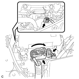
Install the transmission control cable assembly to the No. 1 transmission control cable bracket
Text in Illustration *1 No. 1 Transmission Control Cable Assembly *2 No. 1 Transmission Control Cable Bracket *a Claw A *b Claw B Note
-
Make sure that the claws A on the clip are securely fit into the bracket holes.
-
Make sure that the cable is securely installed inside of the claws B of the clip.
-
-
Connect the transmission control cable assembly to the control shaft lever with the nut.
- Torque:
- 15 N*m { 153 kgf*cm, 11 ft.*lbf }
-
-
INSTALL NO. 4 ENGINE WIRE
-
Install the 3 wire harness clamps and connect the No. 4 engine wire to the fan shroud.
-
-
INSTALL INVERTER WITH CONVERTER ASSEMBLY
CAUTION:
Wear insulated gloves.
-
Temporarily install the inverter with converter assembly with the 2 bolts and nut.
Note
-
Since the inverter with converter assembly is very heavy, 2 people are needed to install the inverter with converter assembly. When installing the inverter with converter assembly, do not damage the parts around it.
-
To prevent damage, do not hold the inverter with converter assembly by the connectors.
-
To prevent damage due to static electricity, do not touch the terminals of the disconnected connectors.
-
-
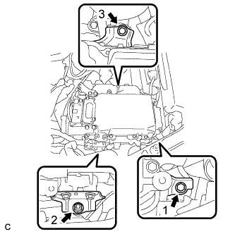
Fully tighten the 2 bolts and nut in the order shown in the illustration.
- Torque:
- 21 N*m { 214 kgf*cm, 15 ft.*lbf }
-
-
CONNECT ENGINE WIRE
-
Connect the wire harness clamp.
-
Connect the connector to the ECM with the lock lever.
-
Install the earth wire with the bolt.
- Torque:
- 8.0 N*m { 82 kgf*cm, 71 in.*lbf }
-
Connect the 4 connectors and wire harness clamp.
-
-
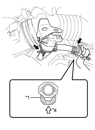
CONNECT NO. 1 INVERTER COOLING HOSE ASSEMBLY
-
Connect the No. 1 inverter cooling hose assembly to the inverter with converter assembly and lock the hose with the retainer.
Text in Illustration *1 Retainer Note
-
Insert the retainer until a click sound is heard.
-
Pull on the hose to confirm that the hose is securely connected.
-
If there is foreign matter on the union or the O-ring, clean it with water and finger scouring.
-
To prevent foreign matter from entering the cooling system, do not remove the pieces of cloth or plastic bags from the pipes and disconnected hoses until installation.
-
-
-
CONNECT NO. 4 INVERTER COOLING HOSE
-
Connect the No. 4 inverter cooling hose assembly to the inverter with converter assembly and lock the hose with the retainer.
Text in Illustration *1 Retainer Note
-
Insert the retainer until a click sound is heard.
-
Pull on the hose to confirm that the hose is securely connected.
-
If there is foreign matter on the union or the O-ring, clean it with water and finger scouring.
-
To prevent foreign matter from entering the cooling system, do not remove the pieces of cloth or plastic bags from the pipes and disconnected hoses until installation.
-
-
-
CONNECT NO. 3 ENGINE ROOM WIRE
-
Connect the clamp.
-
Install the No. 3 engine room wire with the nut.
- Torque:
- 8.0 N*m { 82 kgf*cm, 71 in.*lbf }
-
Install the relay block cover.
-
-
CONNECT LOW VOLTAGE CONNECTOR
-
Connect the 3 low voltage connectors and lock the connector with the lock lever.
Note
-
Do not allow any foreign objects or water to enter the inverter with converter assembly.
-
Make sure that the connectors are fully engaged.
-
-
-
REMOVE CONNECTOR COVER ASSEMBLY
CAUTION:
Wear insulated gloves.
-
Remove the bolt and connector cover assembly.
Note
-
Make sure to pull the connector cover assembly straight up, as a connector is connected to the bottom of the cover.
-
Do not allow any foreign objects or water to enter the inverter with converter assembly.
-
-
-
CONNECT NO. 4 FLOOR WIRE
CAUTION:
Wear insulated gloves.
Note
-
Do not damage the terminals, connector housings or inverter with converter assembly when connecting them.
-
Do not touch the connector waterproofing rubber or terminals.
-
Make sure that the connectors are fully engaged.
-
Do not allow any foreign objects or water to enter the inverter with converter assembly.
-
Make sure that the connector does not come out when its body is pulled.
-
Connect the No. 4 floor wire and wire harness clamp to the inverter with converter assembly.
-
Secure the No. 4 floor wire to the inverter with converter assembly with the bolt.
- Torque:
- 8.0 N*m { 82 kgf*cm, 71 in.*lbf }
-
-
CONNECT NO. 4 ENGINE WIRE
CAUTION:
Wear insulated gloves.
Note
-
Do not damage the terminals, connector housings or inverter with converter assembly when connecting them.
-
Do not touch the connector waterproofing rubber or terminals.
-
Make sure that the connectors are fully engaged.
-
Do not allow any foreign objects or water to enter the inverter with converter assembly.
-
Make sure that the connector does not come out when its body is pulled.
-
Connect the No. 4 engine wire to the inverter with converter assembly.
-
Connect the wire harness clamp.
-
-
INSTALL CONNECTOR COVER ASSEMBLY
CAUTION:
Wear insulated gloves.
Note
-
Make sure that the interlock is fully engaged.
-
Do not allow any foreign objects or water to enter the inverter with converter assembly.
-
Install the connector cover assembly with the 2 bolts.
- Torque:
- 8.0 N*m { 82 kgf*cm, 71 in.*lbf }
-
-
INSTALL NO. 3 MOTOR CABLE BRACKET
-
Install the No. 3 motor cable bracket with the 2 bolts.
- Torque:
- 8.0 N*m { 82 kgf*cm, 71 in.*lbf }
-
Connect the hose clamp.
-
-
CONNECT MOTOR CABLE
CAUTION:
Wear insulated gloves.
Note
-
Do not damage the terminals, connector housings or inverter with converter assembly when connecting them.
-
Do not touch the connector waterproofing rubber or terminals.
-
Do not allow any foreign objects or water to enter the inverter with converter assembly.
-
Connect the motor cable to the inverter with converter assembly.
-
Connect the 3 wire harness clamps.
-
Using an insulated tool, install the 3 bolts and motor cable to the inverter with converter assembly.
- Torque:
- 8.0 N*m { 82 kgf*cm, 71 in.*lbf }
Note
-
The connector should be connected securely.
-
The bolts should be tightened securely.
-
-
INSTALL UPPER INVERTER COVER
CAUTION:
Wear insulated gloves.
-
Install the upper inverter cover (motor cable side) with the 2 bolts.
- Torque:
- 8.0 N*m { 82 kgf*cm, 71 in.*lbf }
Note
-
Do not touch the upper inverter cover waterproofing rubber.
-
Visually confirm that the upper inverter cover waterproofing rubber is securely installed before installing the upper inverter cover.
-
Make sure that the interlock is fully engaged.
-
-
CONNECT GENERATOR CABLE
CAUTION:
Wear insulated gloves.
Note
-
Do not damage the terminals, connector housings or inverter with converter assembly when connecting them.
-
Do not touch the connector waterproofing rubber or terminals.
-
Do not allow any foreign objects or water to enter the inverter with converter assembly.
-
Connect the generator cable to the inverter with converter assembly.
-
Connect the 2 wire harness clamps.
-
Using a insulated tool, install the 3 bolts and generator cable to the inverter with converter assembly.
- Torque:
- 8.0 N*m { 82 kgf*cm, 71 in.*lbf }
Note
-
The connector should be connected securely.
-
The bolts should be tightened securely.
-
-
INSTALL UPPER INVERTER COVER
CAUTION:
Wear insulated gloves.
-
Install the upper inverter cover (motor cable side) with the 2 bolts.
- Torque:
- 8.0 N*m { 82 kgf*cm, 71 in.*lbf }
Note
-
Do not touch the upper inverter cover waterproofing rubber.
-
Visually confirm that the upper inverter cover waterproofing rubber is securely installed before installing the upper inverter cover.
-
Make sure that the interlock is fully engaged.
-
-
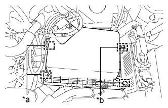
INSTALL NO. 4 INVERTER BRACKET
-
Temporarily install the No. 4 inverter bracket with the 3 bolts.
-
Tighten the 3 bolts in the order shown in the illustration.
- Torque:
- 10 N*m { 102 kgf*cm, 7 ft.*lbf }
-
-
INSTALL NO. 5 INVERTER BRACKET
-
Temporarily install the No. 5 inverter bracket with the 2 bolts.
-
Tighten the 2 bolts in the order shown in the illustration.
- Torque:
- 10 N*m { 102 kgf*cm, 7 ft.*lbf }
-
-
INSTALL AIR CLEANER CASE SUB-ASSEMBLY
-
Insert the projection of the air cleaner case sub-assembly to the hole of the No. 2 air cleaner bracket as shown in the illustration.
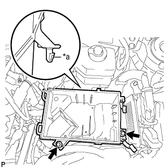
Text in Illustration *a Projection -
Tighten the 2 bolts.
- Torque:
- 5.0 N*m { 51 kgf*cm, 44 in.*lbf }
-
-
INSTALL AIR CLEANER FILTER ELEMENT
-
Install the air cleaner filter element.
Note
Install the air cleaner filter element with the printed side facing the vehicle front.
-
-
INSTALL AIR CLEANER CAP SUB-ASSEMBLY
-
Install the air cleaner hose with the hose clamp.
-
Connect the 2 fuel vapor feed hoses.
Text in Illustration *1 Retainer *a Push Note
-
Check that there are no scratches or foreign matter around the connected part of the fuel tube connector and pipe before performing this work.
-
Connect the quick connector and push the retainer in until the retainer makes a "click" sound to lock the claws of the retainer.
-
After connecting the fuel vapor feed hose to the fuel tube connector, check that the fuel vapor feed hose is securely connected by pulling on the fuel tube connector and the fuel vapor feed hose.
-
-
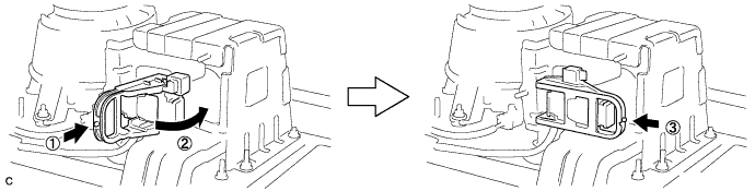
Connect the 2 hinges of the air cleaner cap subassembly.
Text in Illustration *a Hinge *b Clamp -
Install the air cleaner cap sub-assembly with the 2 clamps.
-
Connect the wire harness clamp and connector.
-
Connect the ventilation hose to the cylinder head cover.
-
Connect the mass air flow meter connector and wire harness clamp to the air cleaner cap sub-assembly.
-
-
INSTALL INLET AIR CLEANER ASSEMBLY
-
Install the inlet air cleaner assembly with the 2 bolts.
- Torque:
- 8.0 N*m { 82 kgf*cm, 71 in.*lbf }
-
-
INSTALL SERVICE PLUG GRIP
CAUTION:
Wear insulating gloves.
Note
Before connecting the service plug, check that no parts and tools remain and that the high voltage terminals and connectors are connected securely.
-
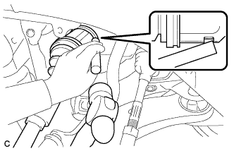
Wear insulated gloves and install the service plug grip in the order shown in the illustration.
-
Rotate the handle of the service plug grip 90° toward the battery and slide it in the direction shown by the arrow until a click sound is heard.
-
-
INSTALL NO. 8 HYBRID VEHICLE BATTERY SHIELD PANEL
-
Install the No. 8 hybrid vehicle battery shield panel with the 2 nuts.
- Torque:
- 7.5 N*m { 76 kgf*cm, 66 in.*lbf }
-
-
INSTALL LUGGAGE COMPARTMENT FRONT TRIM COVER
-
Engage the 2 claws.
-
Engage the 8 fasteners and install the luggage compartment front trim cover.
-
-
INSTALL BAGGAGE HOLDER NET (w/ Partition Net)
-
Install the baggage holder net.
-
-
INSTALL SPARE WHEEL COVER ASSEMBLY
-
Install the spare wheel cover assembly.
-
-
CONNECT CABLE TO AUXILIARY BATTERY NEGATIVE TERMINAL
Note
When disconnecting the cable, some systems need to be initialized after the cable is reconnected Click here.
-
INSTALL LUGGAGE TRIM SERVICE HOLE COVER
-
Engage the claw to connect the luggage trim service hole cover.
-
-
ADD ENGINE OIL
-
Add new oil.
Standard Oil Grade Oil Grade Oil Viscosity ILSAC multigrade engine oil 0W-20 Standard Oil Grade (Destination package for South Korea) Oil Grade Oil Viscosity (SAE) -
API grade SL "energy-conserving", SM "energy-conserving", SN "resource-conserving" or ILSAC multigrade engine oil
-
0W-20
-
5W-20
-
5W-30
-
10W-30
API grade SL, SM or SN multigrade engine oil -
15W-40
-
20W-50
Standard Capacity Item Specified Condition Drain and refill (with oil filter change) 4.4 liters (4.6 US qts, 3.9 Imp. qts) Drain and refill (without oil filter change) 4.0 liters (4.2 US qts, 3.5 Imp. qts) Dry fill 5.3 liters (5.6 US qts, 4.7 Imp. qts) -
-
Install the oil filler cap.
-
-
ADD COOLANT (for Engine)
-
Tighten the radiator drain cock plug by hand.
-
Slowly fill the radiator with TOYOTA Super Long Life Coolant (SLLC).
Item Capacity Engine coolant 7.2 liters (7.6 US qts, 6.3 Imp. qts) Note
Never use water as a substitute for engine coolant.
Tech Tips
TOYOTA vehicles are filled with TOYOTA SLLC at the factory. In order to avoid damage to the engine cooling system and other technical problems, only use TOYOTA SLLC or similar high quality ethylene glycol based non-silicate, non-amine, non-nitrite, non-borate coolant with long-life hybrid organic acid technology (coolant with long-life hybrid organic acid technology is a combination of low phosphates and organic acids).
-
Slowly pour coolant into the radiator reserve tank assembly until it reaches the full line.
-
Squeeze the No. 1 and No. 2 radiator hoses several times by hand, and then check the level of the coolant.
If the coolant level is low, add coolant.
-
Install the radiator cap sub-assembly and reserve tank cap.
-
Put the engine in inspection mode Click here.
-
Bleed air from the cooling system.
Note
-
Before starting the engine, turn the A/C switch off.
-
Adjust the heater control to the maximum hot setting.
-
Adjust the blower speed to the low setting.
-
Warm up the engine until the thermostat opens. While the thermostat is open, circulate the coolant for several minutes.
Tech Tips
The thermostat open timing can be confirmed by squeezing the No. 2 radiator hose by hand, and sensing vibrations when the engine coolant starts to flow inside the hose.
-
Squeeze the No. 1 and No. 2 radiator hoses several times by hand to bleed air.
CAUTION:
When squeezing the radiator hoses:
-
Wear protective gloves.
-
Be careful as the radiator hoses are hot.
-
Keep your hands away from the cooling fans.
Note
-
Make sure that the radiator reserve tank assembly still has some coolant in it.
-
If the coolant temperature gauge indicates an excessive temperature, turn off the engine and let it cool.
-
If there is not enough coolant, the engine may overheat or be seriously damaged.
-
If the radiator reserve tank assembly does not have enough coolant, perform the following: 1) stop the engine, 2) wait until the coolant has cooled down, and 3) add coolant until the reserve tank assembly is filled to the full line.
-
-
-
Stop the engine and wait until the engine coolant cools down.
-
Add engine coolant to the full line on the radiator reserve tank assembly.
-
-
ADD COOLANT (for Inverter)
Note
-
Do not reuse the drained coolant because it may contain foreign objects.
-
If the vehicle is driven with air in the inverter cooling system, damage may occur and the following DTCs may be set.
DTC Code Detection Item P0A01-726 Motor Electronics Coolant Temperature Sensor Circuit Range / Performance P0A04-725 Motor Electronics Coolant Temperature Sensor Circuit Intermittent P0A08-264 DC / DC Converter Status Circuit P0A78-284 Drive Motor "A" Inverter Performance P0A78-286 Drive Motor "A" Inverter Performance P0A7A-322 Generator Inverter Performance P0A7A-324 Generator Inverter Performance P0A93-346 Inverter Cooling System Performance P0A94-553 DC / DC Converter Performance P0A94-557 DC / DC Converter Performance P0AEE-277 Motor Inverter Temperature Sensor "A" Circuit Range / Performance P0AF1-276 Drive Motor Inverter Temperature Sensor "A" Circuit Intermittent / Erratic P0BCD-315 Generator Inverter Temperature Sensor Circuit Range / Performance P0BD0-314 Generator Inverter Temperature Sensor Circuit Intermittent / Erratic P0C39-626 DC / DC Converter Temperature Sensor "A" Range / Performance P0C3C-625 DC / DC Converter Temperature Sensor "A" Intermittent / Erratic P0C3E-628 DC / DC Converter Temperature Sensor "B" Range / Performance P0C41-627 DC / DC Converter Temperature Sensor "B" Intermittent / Erratic P0C73-776 Motor Electronics Coolant Pump "A" Control Performance
-
Slowly pour coolant into the reserve tank until it reaches the FULL line.
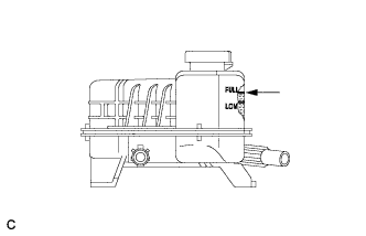
Coolant quantity 3.2 liters (3.4 US qts, 2.8 Imp. qts.) Note
To prevent foreign matter such as dust or dirt from entering the cooling system, make sure to confirm that the container used to add coolant is clean and free of foreign matter such as dust or dirt.
-
When using the Techstream:
-
Connect the Techstream to the DLC3.
-
Turn the power switch on (IG).
-
Enter the following menus: Powertrain / Hybrid Control / Active Test / Activate the Water Pump.
-
Keep the coolant at the FULL line in the reserve tank to compensate for the drop in coolant level when the air bleeds.
Standard Air bleeding from the inverter cooling system is completed when the noise made by the inverter water pump assembly becomes smaller and the circulation of coolant in the reserve tank improves. Tech Tips
-
If free spinning of the inverter water pump is detected for approximately 5 seconds, failsafe control will be activated to suspend the operation of the pump for approximately 15 seconds and resume operation for approximately 4 seconds repeatedly. Operation of the inverter water pump will return to normal if coolant is added.
-
Loud noise made by the inverter water pump assembly and poor circulation of coolant in the reserve tank indicates that there is air in the cooling system.
Tech Tips
Loud noise made by the water pump and poor circulation of coolant in the reserve tank indicates that there is air in the cooling system.
-
-
-
When not using the Techstream:
-
Turn the power switch on (READY).[*1]
-
Turn the power switch off and add coolant to the FULL line because the coolant level drops as the air bleeds.[*2]
Note
-
Be sure to turn the power switch off before adding SLLC.
-
Do not work on the components in the engine compartment while the vehicle is in the READY-on state because the engine is in intermittent operation.
-
-
Repeat steps [*1] and [*2] until air bleeding from the cooling system is completed.
Standard Air bleeding from the inverter cooling system is completed when the noise made by the inverter water pump assembly becomes smaller and the circulation of coolant in the reserve tank improves. Tech Tips
Loud noise made by the water pump and poor circulation of coolant in the reserve tank indicates that there is air in the cooling system.
-
-
After the air is completely bled from the cooling system, tighten the reserve tank cap.
-
Add coolant to the FULL line of the reserve tank.
-
-
ADD HYBRID TRANSAXLE FLUID
-
CHARGE AIR CONDITIONING SYSTEM WITH REFRIGERANT
-
Perform vacuum purging using a vacuum pump or appropriate equipment.
-
Charge the air conditioning system with refrigerant.
Refrigerant type HFC-134a (R134a) 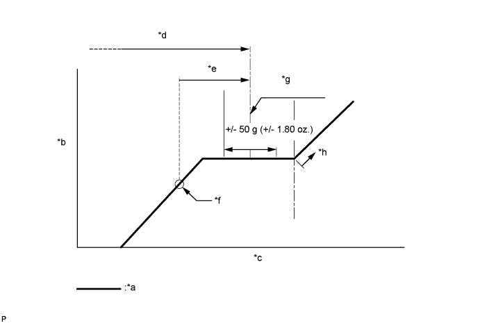
Text in Illustration *a Sub-cool System *b High Pressure *c Refrigerant Amount *d Standard charge amount *e Charge additional 100g (3.5oz.) *f Point where bubbles disappear *g Mean value in proper range *h Overcharged Standard charge amount 480 to 580g (16.9 to 20.4oz.) - SST
- 09985-20010 ( 09985-02010, 09985-02050, 09985-02060, 09985-02070, 09985-02080, 09985-02090, 09985-02110, 09985-02130, 09985-02140, 09985-02150 )
Note
-
Do not turn the A/C switch on before charging the air conditioning system with refrigerant. Doing so may cause the compressor to work without refrigerant, resulting in overheating of the compressor.
-
The refrigerant amount should be checked by quantity (weight).
-
The graph above is shown for reference only. This vehicle is not equipped with a sight glass.
Tech Tips
Ensure that sufficient refrigerant is available to recharge the system when using a refrigerant recovery unit. Refrigerant recovery units are not always able to recover 100% of the refrigerant from an air conditioning system.
-
-
WARM UP ENGINE
-
INSPECT FOR FUEL LEAK
-
Check fuel pump operation.
-
Connect the Techstream to the DLC3.
-
Turn the power switch to on (IG) and turn the Techstream on.
Note
Do not start the engine.
-
Enter the following menus: Powertrain / Engine and ECT / Active Test / Control the Fuel Pump / Speed.
-
Check for pressure in the fuel inlet tube from the fuel line. Check that sounds of fuel flowing from the fuel tank can be heard. If no sounds can be heard, check the integration relay, fuel pump, ECM and wiring connectors.
-
-
Inspect for fuel leaks.
-
Check that there are no fuel leaks from the fuel system after doing any maintenance or repairs. If there is a fuel leak, repair or replace parts as necessary.
-
-
Turn the power switch off.
-
Disconnect the Techstream from the DLC3.
-
-
INSPECT FOR OIL LEAK
-
INSPECT FOR COOLANT LEAK
Note
Before performing each inspection, turn the A/C switch off.
-
Fill the radiator with coolant and attach a radiator cap tester.
-
Put the engine in inspection mode Click here.
-
Warm up the engine.
-
Using a radiator cap tester, increase the pressure inside the radiator to 118 kPa (1.2 kgf/cm2, 17 psi), and check that the pressure does not drop.
If the pressure drops, check the hoses, radiator and water pump for leaks. If no external leaks are found, check the heater core, cylinder block and cylinder head.
-
-
INSPECT FOR EXHAUST GAS LEAK
-
INSPECT REFRIGERANT LEAK
-
After recharging the air conditioning system with refrigerant, inspect for refrigerant leaks using a halogen leak detector.
-
Carry out the test under the following conditions:
-
Turn the power switch off.
-
Secure good ventilation (the halogen leak detector may react to volatile gases which are not refrigerant, such as gasoline vapor and exhaust gas).
-
Repeat the inspection 2 or 3 times.
-
Measure the pressure to make sure that there is some refrigerant remaining in the air conditioning system.
Pressure when the compressor is off: approx. 392 to 588 kPa (3.9 to 5.9 kgf/cm2, 57 to 85 psi)
-
-
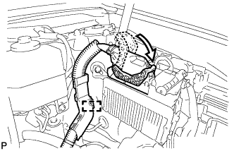
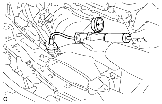
Using a halogen leak detector, inspect for refrigerant leaks from the air conditioning system.
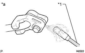
Text in Illustration *1 Halogen Leak Detector *a Inspect for Leak -
Bring the halogen leak detector close to the drain hose with the detector power off, and then turn the detector on.
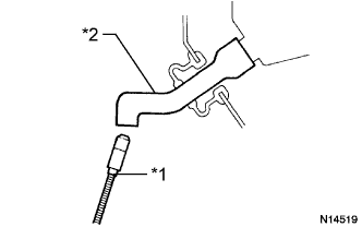
Text in Illustration *1 Halogen Leak Detector *2 Drain Hose Tech Tips
-
After the blower motor has stopped, leave the cooling unit for more than 15 minutes.
-
Bring the halogen leak detector sensor under the drain hose.
-
When bringing the halogen leak detector close to the drain hose, make sure that the halogen leak detector does not react to volatile gases. If it is not possible to avoid interference from volatile gases, the vehicle should be lifted up to allow checking for leaks.
-
-
If a refrigerant leak is not detected from the drain hose, remove the blower motor control from the cooling unit. Insert the halogen leak detector sensor into the unit and check for a leak.
-
Disconnect the pressure sensor connector and leave it for approximately 20 minutes. Bring the halogen leak detector close to the pressure sensor and check for a leak.
Tech Tips
When checking for leaks, the presence of oily dirt at a joint can indicate a leak.
-
-
INSPECT IGNITION TIMING
-
Put the engine in inspection mode Click here.
-
Warm up and stop the engine.
-
When using the Techstream:
Check the ignition timing.
-
Connect the Techstream to the DLC3.
-
Put the engine in inspection mode Click here.
-
Enter the following menus: Powertrain / Engine and ECT / Data List / IGN Advance.
Standard ignition timing 5 to 20 degrees BTDC Note
-
Check the ignition timing with the cooling fans off.
-
Turn off all electrical systems and the A/C.
-
When checking the ignition timing, the shift lever should be in P.
Tech Tips
Refer to the Techstream operator's manual for further details.
-
-
Check that the ignition timing advances immediately when the engine speed is increased.
-
Enter the following menus: Powertrain / Engine and ECT / Active Test / Connect the TC and TE1 / ON.
-
Monitor IGN Advance of the Data List.
Standard ignition timing 8 to 12 degrees BTDC Note
When checking the ignition timing, the shift lever should be in P.
Tech Tips
Refer to the Techstream operator's manual for further details.
-
Enter the following menus: Connect the TC and TE1 / OFF.
-
Turn the power switch off.
-
Turn the Techstream off.
-
Disconnect the Techstream from the DLC3.
-
-
When not using the Techstream:
-
Using SST, connect terminals 13 (TC) and 4 (CG) of the DLC3.
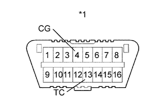
Text in Illustration *1 DLC3 - SST
- 09843-18040
Note
-
Confirm the terminals before connecting them. Connecting the wrong terminals may result in damage to electrical components.
-
Check the ignition timing with the cooling fans off.
-
Turn off all electrical systems and the A/C.
-
When checking the ignition timing, the shift lever should be in P.
-
Remove the No. 1 engine cover sub-assembly.
-
Pull out the wire harness.
Note
After checking, wrap the wire harness with tape.
-
Connect the clip of the timing light to the wire harness.
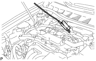
Note
Use a timing light that detects the primary signal.
-
Inspect the ignition timing at idle.
Standard ignition timing 8 to 12 degrees BTDC Note
When checking the ignition timing, the shift lever should be in P.
Tech Tips
After running the engine at 1000 to 1300 rpm for 5 seconds, check that it returns to idle speed.
-
Disconnect terminals 13 (TC) and 4 (CG) of the DLC3.
-
Inspect the ignition timing at idle.
Standard ignition timing 5 to 20 degrees BTDC -
Confirm that the ignition timing advances when the engine rpm is increased.
-
Remove the timing light.
-
Install the No. 1 engine cover sub-assembly.
-
-
-
INSPECT ENGINE IDLE SPEED
-
Put the engine in inspection mode Click here.
-
Warm up and stop the engine.
-
When using the Techstream:
-
Connect the Techstream to the DLC3.
-
Put the engine in inspection mode Click here.
-
Enter the following menus: Powertrain / Engine and ECT / Data List / Engine Speed.
Tech Tips
Refer to the Techstream operator's manual for further details.
-
Inspect the engine idle speed.
Standard idle speed 900 to 1050 rpm Note
-
Turn all electrical systems and the A/C off.
-
Inspect the idle speed with the cooling fans off.
-
When checking the ignition timing, the shift lever should be in P.
-
-
Turn the power switch off.
-
Turn the Techstream off.
-
Disconnect the Techstream from the DLC3.
-
-
When not using the Techstream:
-
Using SST, connect a tachometer tester probe to terminal 9 (TAC) of the DLC3.
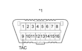
Text in Illustration *1 DLC3 - SST
- 09843-18030
-
Put the engine in inspection mode Click here.
-
Inspect the engine idle speed.
Standard idle speed 900 to 1050 rpm Note
-
Turn all electrical systems and the A/C off.
-
Inspect the idle speed with the cooling fans off.
-
When checking the ignition timing, the shift lever should be in P.
-
-
Disconnect the tachometer probe from the DLC3.
-
-
-
INSPECT CO/HC
Tech Tips
This check determines whether or not the idle CO / HC complies with regulations.
-
Put the engine in inspection mode Click here.
-
Warm up the engine.
-
Run the engine at 2500 rpm for approximately 180 seconds.
-
Insert a CO/HC meter testing probe at least 40 cm (1.31 ft.) into the tailpipe while idling.
-
Check the CO/HC concentration while idling and when the engine is running at 2500 rpm.
Tech Tips
When doing a 2 mode (with the engine idling/ running at 2500 rpm) test, the measurement procedures are determined by applicable local regulations.
If the CO/HC concentration does not comply with the regulations, troubleshoot in the order given below.
-
Check the DTCs Click here.
-
See the table below for possible causes, then inspect the applicable parts and repair them if necessary.
CO HC Problem Possible Cause Normal High Rough idle -
Faulty ignition:
-
Incorrect timing
-
Fouled, shorted or improperly gapped plugs
-
Incorrect valve clearance
-
Leaks from intake and exhaust valves
-
Leaks from cylinders
-
Faulty EGR
Low High Rough idle (Fluctuating HC reading) -
Vacuum leaks:
-
PCV hoses
-
Intake manifold
-
Throttle body
-
Lean mixture causing misfire
-
Faulty EGR
High High Rough idle (Black smoke from exhaust) -
Restricted air cleaner filter element
-
Plugged PCV valve
-
Faulty EFI systems:
-
Faulty pressure regulator
-
Faulty engine coolant temperature sensor
-
Faulty mass air flow meter
-
Faulty ECM
-
Faulty injectors
-
Throttle body
-
Faulty EGR
-
-
-
-
INSTALL NO. 1 ENGINE COVER SUB-ASSEMBLY
-
Engage the 3 pins and install the No. 1 engine cover sub-assembly.
-
-
INSTALL COOL AIR INTAKE DUCT SEAL
-
Install the cool air intake duct seal with the 7 clips.
-
-
INSPECT AND ADJUST SHIFT LEVER POSITION
-
INSTALL FRONT FENDER APRON SEAL LH
-
INSTALL FRONT FENDER APRON SEAL RH
-
INSTALL ENGINE UNDER COVER LH
-
INSTALL FRONT WHEEL OPENING EXTENSION PAD LH
-
INSTALL ENGINE UNDER COVER RH
-
INSTALL FRONT WHEEL OPENING EXTENSION PAD RH
-
INSTALL FRONT WHEEL
- Torque:
- 103 N*m { 1049 kgf*cm, 76 ft.*lbf }
-
CHECK ABS SPEED SENSOR SIGNAL
-
INSPECT AND ADJUST FRONT WHEEL ALIGNMENT