HYBRID CONTROL SYSTEM, Diagnostic DTC:P314A-828

| DTC Code | DTC Name |
|---|---|
| P314A-828 | Inverter Coolant Pump Speed Signal |
DESCRIPTION
Refer to the description for DTC P0C73-776 Click here.
| DTC No. | INF Code | DTC Detection Condition | Trouble Area |
|---|---|---|---|
| P314A | 828 | Open in the water pump speed signal line or water pump power source circuit. |
|
MONITOR DESCRIPTION
The power management control ECU monitors speed of the inverter water pump assembly. If there is an abnormality in speed, the power management control ECU will illuminate the MIL and set a DTC.
MONITOR STRATEGY
| Related DTCs | P314A (INF 828): Water pump malfunction |
| Required sensors / components | Inverter Water Pump Assembly |
| Frequency of operation | Continuous |
| Duration | TMC's intellectual property |
| MIL operation | Immediately |
| Sequence of operation | None |
TYPICAL ENABLING CONDITIONS
| The monitor will run whenever the following DTCs are not present | TMC's intellectual property |
| Other conditions belong to TMC's intellectual property | - |
TYPICAL MALFUNCTION THRESHOLDS
| TMC's intellectual property | - |
COMPONENT OPERATING RANGE
| Power management control ECU | DTC P314A (INF 828) is not detected |
CONFIRMATION DRIVING PATTERN
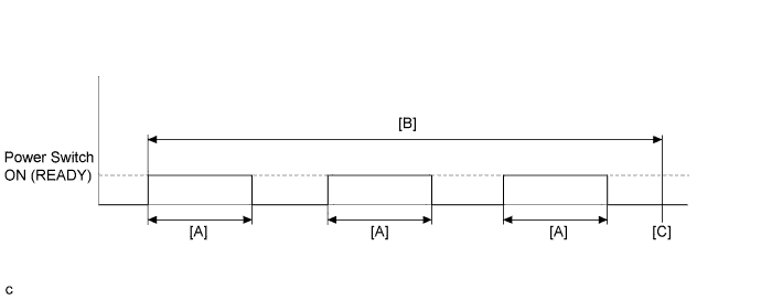
-
Connect the Techstream to the DLC3.
-
Turn the power switch on (IG) and turn the Techstream on.
-
Clear the DTCs (even if no DTCs are stored, perform the clear DTC procedure).
-
Turn the power switch off.
-
Turn the power switch on (READY) and after a few seconds, turn the power switch off. [A]
-
Repeat [A] 3 times. [B]
-
Turn the power switch on (IG) and turn the Techstream on.
-
Enter the following menus: Powertrain / Hybrid Control / Trouble Codes. [C]
-
Check that permanent DTCs are cleared.
-
If the permanent DTCs are not cleared, perform the universal trip, and then check for permanent DTCs again.
Tech Tips
-
If a permanent DTC is output, the system is malfunctioning.
-
If no permanent DTC is output, the system is normal.
WIRING DIAGRAM
Refer to the wiring diagram for DTC P0C73-776 Click here.
INSPECTION PROCEDURE
Note
If DTC P0A78-284, 286, P0A7A-322, 324, P0A94-553 or 557 is output, replace the inverter with converter assembly after this inspection.
PROCEDURE
-
PERFORM ACTIVE TEST USING TECHSTREAM (ACTIVATE THE WATER PUMP)
Note
Be sure to perform the inspection with the auxiliary battery voltage at 11 V or more.
Tech Tips
When the auxiliary battery voltage is low, the inverter water pump assembly may not operate.
-
Connect the Techstream to the DLC3.
-
Turn the power switch on (IG).
-
Enter the following menus: Powertrain / Hybrid Control / Active Test / Activate the Water Pump.
-
Perform the Activate the Water Pump Active Test.
-
Touch the inverter water pump assembly and check that it is operating (vibrating).
OK The inverter water pump is operating (vibrating). -
Turn the power switch off.
NG 
CHECK FUSE (INV W/PMP) Click here
OK 
-
-
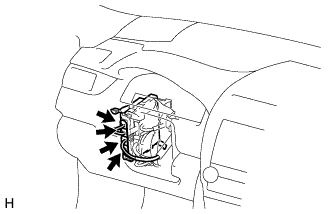
CHECK CONNECTOR CONNECTION CONDITION (POWER MANAGEMENT CONTROL ECU CONNECTOR)
-
Check the connector connections and contact pressure of the relevant terminals for the power management control ECU connectors Click here.
OK The connectors are connected securely and there are no contact pressure problems.
NG 
CONNECT SECURELY
OK
-
-
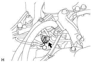
CHECK CONNECTOR CONNECTION CONDITION (INVERTER WATER PUMP ASSEMBLY CONNECTOR)
-
Check the connector connections and contact pressure of the relevant terminals for the inverter water pump assembly connector Click here.
OK The connectors are connected securely and there are no contact pressure problems.
NG
CONNECT SECURELY
OK
-
-
CHECK HARNESS AND CONNECTOR (POWER MANAGEMENT CONTROL ECU - INVERTER WATER PUMP ASSEMBLY)
-
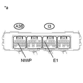
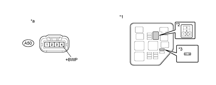
Disconnect connector A38 from the power management control ECU.
-
Disconnect connector A50 from the inverter water pump assembly.
-
Measure the resistance according to the value(s) in the table below.
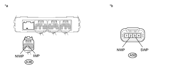
Text in Illustration *a Rear view of wire harness connector
(to Power Management Control ECU)
*b Front view of wire harness connector
(to Inverter Water Pump Assembly)
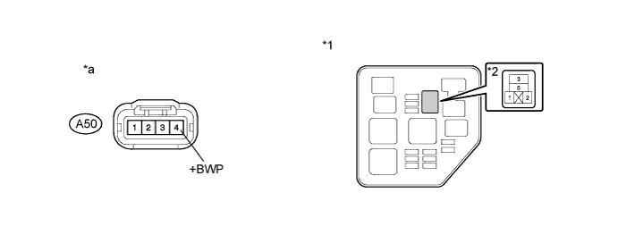
Standard Resistance Tester Connection Switch Condition Specified Condition A38-14 (NIWP) - A50-2 (NWP) Power switch off Below 1 Ω A38-13 (IWP) - A50-3 (SWP) Power switch off Below 1 Ω A38-14 (NIWP) or A50-2 (NWP) -Body ground and other terminals Power switch off 10 kΩ or higher A38-13 (IWP) or A50-3 (SWP) - Body ground and other terminals Power switch off 10 kΩ or higher -
Connect the power management control ECU connector.
-
Connect the inverter water pump assembly connector.
NG
REPAIR OR REPLACE HARNESS OR CONNECTOR
OK
-
-
CHECK POWER MANAGEMENT CONTROL ECU
-
Disconnect connector A50 from the inverter water pump assembly.
-
Turn the power switch on (IG).
-
Measure the voltage according to the value(s) in the table below.
Standard Voltage Tester Connection Switch Condition Specified Condition A38-14 (NIWP) - I3-6 (E1) Power switch on (IG) 11 to 14 V Text in Illustration *a Component with harness connected
(Power Management Control ECU)
-
Turn the power switch off.
-
Connect the inverter water pump assembly connector.
NG
REPLACE POWER MANAGEMENT CONTROL ECU Click here
OK
-
-
PERFORM ACTIVE TEST USING TECHSTREAM (ACTIVATE THE WATER PUMP)
Note
Be sure to perform the inspection with the auxiliary battery voltage at 11 V or more.
Tech Tips
When the auxiliary battery voltage is low, the inverter water pump assembly may not operate.
-
Connect the Techstream to the DLC3.
-
Turn the power switch on (IG).
-
Enter the following menus: Powertrain / Hybrid Control / Active Test / Activate the Water Pump.
-
Perform the "Activate the Water Pump" Active Test.
-
Connect an oscilloscope between the power management control ECU terminals specified in the table below, and measure the waveform.
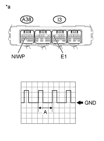
Item Content Terminal A38-14 (NIWP) - I3-6 (E1) Equipment Setting 5 V/DIV., 100 ms./DIV. Condition Power switch on (IG), during Active Test OK The duration of wavelength A is 300 msec or less. Text in Illustration *a Component with harness connected
(Power Management Control ECU)
-
Turn the power switch off.
NG
REPLACE POWER MANAGEMENT CONTROL ECU Click here
OK 
REPLACE INVERTER WATER PUMP ASSEMBLY Click here
-
-
CHECK FUSE (INV W/PMP)
-
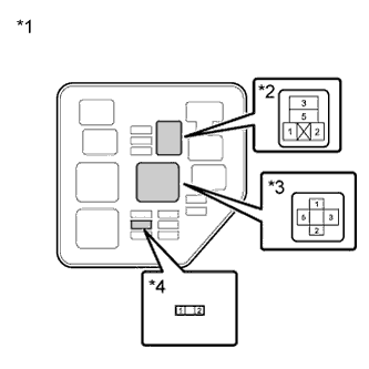
Remove the INV W/PMP fuse from the No. 2 engine room relay block.
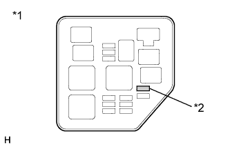
-
Measure the resistance according to the value(s) in the table below.
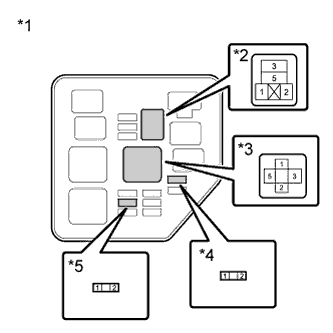
Standard Resistance Tester Connection Condition Specified Condition INV W/PMP fuse Always Below 1Ω Text in Illustration *1 No. 2 Engine Room Relay Block *2 INV W/PMP Fuse -
Install the INV W/PMP fuse.
NG
OK
-
-
CHECK FUSE (INV W/PMP RLY)
-
Remove the INV W/PMP RLY fuse from the No. 2 engine room relay block.
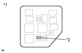
-
Measure the resistance according to the value(s) in the table below.
Standard Resistance Tester Connection Condition Specified Condition INV W/PMP RLY fuse Always Below 1Ω Text in Illustration *1 No. 2 Engine Room Relay Block *2 INV W/PMP RLY Fuse -
Install the INV W/PMP RLY fuse.
NG
OK
-
-
INSPECT RELAY (INV W/PMP)
-
Remove the INV W/PMP relay from the No. 2 engine room relay block.
-
Measure the resistance according to the value(s) in the table below.
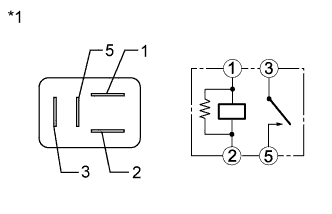
Standard Resistance Tester Connection Condition Specified Condition 3 - 5 Auxiliary battery voltage is not applied between terminals 1 and 2 10 kΩ or higher Auxiliary battery voltage is applied between terminals 1 and 2 Below 1Ω Text in Illustration *1 INV W/PMP Relay -
Install the INV W/PMP relay.
NG
REPLACE RELAY (INV W/PMP)
OK
-
-
CHECK CONNECTOR CONNECTION CONDITION (INVERTER WATER PUMP ASSEMBLY CONNECTOR)
-
Check the connector connections and contact pressure of the relevant terminals for the inverter water pump assembly connector Click here.
OK The connectors are connected securely and there are no contact pressure problems.
NG
CONNECT SECURELY
OK
-
-
CHECK HARNESS AND CONNECTOR (NO. 2 ENGINE ROOM RELAY BLOCK (INVERTER WATER PUMP ASSEMBLY CIRCUIT))
-
Remove the INV W/PMP fuse and INV W/PMP RLY fuse from the No. 2 engine room relay block.
-
Remove the INV W/PMP relay and IGCT relay from the No. 2 engine room relay block.
-
Measure the resistance according to the value(s) in the table below.
Text in Illustration *1 No. 2 Engine Room Relay Block *2 INV W/PMP Relay *3 IGCT Relay *4 INV W/PMP Fuse *5 INV W/PMP RLY Fuse Standard Resistance Tester Connection Switch Condition Specified Condition 2 (INV W/PMP fuse) - 5 (INV W/PMP relay) Power switch off Below 1 Ω 2 (INV W/PMP RLY fuse) - 1 (INV W/PMP relay) Power switch off Below 1 Ω 1 (INV W/PMP RLY fuse) - 5 (IGCT relay) Power switch off Below 1 Ω 2 (INV W/PMP Relay) - Body ground Power switch off Below 1 Ω 2 (INV W/PMP fuse) or 5 (INV W/PMP relay) - Body ground and other terminals Power switch off 10 kΩ or higher 2 (INV W/PMP RLY fuse) or 1 (INV W/PMP relay) - Body ground and other terminals Power switch off 10 kΩ or higher 1 (INV W/PMP RLY fuse) or 5 (IGCT relay) - Body ground and other terminals Power switch off 10 kΩ or higher Note
Do not apply excessive force when using the probes of the tester to perform the inspection. If excessive force is used, the terminals will be damaged.
-
Install the INV W/PMP fuse and INV W/PMP RLY fuse.
-
Install the INV W/PMP relay and IGCT relay.
NG
REPAIR OR REPLACE HARNESS OR CONNECTOR
OK
-
-
CHECK HARNESS AND CONNECTOR (INVERTER WATER PUMP ASSEMBLY - NO. 2 ENGINE ROOM RELAY BLOCK)
-
Remove the INV W/PMP relay from the No. 2 engine room relay block.
-
Disconnect connector A50 from the inverter water pump assembly.
-
Measure the resistance according to the value(s) in the table below.
Text in Illustration *1 No. 2 Engine Room Relay Block *2 INV W/PMP Relay *a Front view of wire harness connector
(to Inverter Water Pump Assembly)
- - Standard Resistance Tester Connection Switch Condition Specified Condition A50-4 (+BWP) - 3 (INV W/PMP relay) Power switch off Below 1 Ω A50-4 (+BWP) or 3 (INV W/PMP relay) - Body ground and other terminals Power switch off 10 kΩ or higher Note
Do not apply excessive force when using the probes of the tester to perform the inspection. If excessive force is used, the terminals will be damaged.
-
Install the INV W/PMP relay.
-
Connect the inverter water pump assembly connector.
NG
REPAIR OR REPLACE HARNESS OR CONNECTOR
OK
-
-
CHECK HARNESS AND CONNECTOR (POWER MANAGEMENT CONTROL ECU - INVERTER WATER PUMP ASSEMBLY)
-
Disconnect connector A38 from the power management control ECU.
-
Disconnect connector A50 from the inverter water pump assembly.
-
Measure the resistance according to the value(s) in the table below.
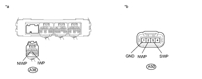
Text in Illustration *a Rear view of wire harness connector
(to Power Management Control ECU)
*b Front view of wire harness connector
(to Inverter Water Pump Assembly)
Standard Resistance Tester Connection Switch Condition Specified Condition A38-14 (NIWP) - A50-2 (NWP) Power switch off Below 1 Ω A38-13 (IWP) - A50-3 (SWP) Power switch off Below 1 Ω A50-1 (GND) - Body ground Power switch off Below 1 Ω A38-14 (NIWP) or A50-2 (NWP) - Body ground and other terminals Power switch off 10 kΩ or higher A38-13 (IWP) or A50-3 (SWP) - Body ground and other terminals Power switch off 10 kΩ or higher -
Connect the power management control ECU connector.
-
Connect the inverter water pump assembly connector.
NG
REPAIR OR REPLACE HARNESS OR CONNECTOR
OK
REPLACE INVERTER WATER PUMP ASSEMBLY Click here
-
-
CHECK CONNECTOR CONNECTION CONDITION (INVERTER WATER PUMP ASSEMBLY CONNECTOR)
-
Check the connector connections and contact pressure of the relevant terminals for the inverter water pump assembly connector Click here.
OK The connectors are connected securely and there are no contact pressure problems.
NG
CONNECT SECURELY Click here
OK
-
-
CHECK HARNESS AND CONNECTOR (INVERTER WATER PUMP ASSEMBLY - NO. 2 ENGINE ROOM RELAY BLOCK)
-
Remove the INV W/PMP fuse from the No. 2 engine room relay block.
Text in Illustration *1 No. 2 Engine Room Relay Block *2 INV W/PMP Fuse -
Remove the INV W/PMP relay from the No. 2 engine room relay block.
-
Disconnect connector A50 from the inverter water pump assembly.
-
Measure the resistance according to the value(s) in the table below.
Text in Illustration *1 No. 2 Engine Room Relay Block *2 INV W/PMP Relay *3 INV W/PMP Fuse - - *a Front view of wire harness connector
(to Inverter Water Pump Assembly)
- - Standard Resistance Tester Connection Switch Condition Specified Condition A50-4 (+BWP) or 3 (INV W/PMP relay) - Body ground and other terminals Power switch off 10 kΩ or higher 5 (INV W/PMP relay) or 2 (INV W/PMP fuse) - Body ground and other terminals Power switch off 10 kΩ or higher Note
Do not apply excessive force when using the probes of the tester to perform the inspection. If excessive force is used, the terminals will be damaged.
-
Install the INV W/PMP fuse.
-
Install the INV W/PMP relay.
-
Connect the inverter water pump assembly connector.
NG
REPAIR OR REPLACE HARNESS OR CONNECTOR Click here
OK
-
-
REPLACE INVERTER WATER PUMP ASSEMBLY
NEXT
REPLACE FUSE (INV W/PMP)
-
CHECK CONNECTOR CONNECTION CONDITION (INVERTER WATER PUMP ASSEMBLY CONNECTOR)
-
Check the connector connections and contact pressure of the relevant terminals for the inverter water pump assembly connector Click here.
OK The connectors are connected securely and there are no contact pressure problems.
NG
CONNECT SECURELY Click here
OK
-
-
CHECK HARNESS AND CONNECTOR (NO. 2 ENGINE ROOM RELAY BLOCK (INVERTER WATER PUMP ASSEMBLY CIRCUIT))
-
Remove the INV W/PMP RLY fuse from the No. 2 engine room relay block.
-
Remove the INV W/PMP relay and IGCT relay from the No. 2 engine room relay block.
-
Measure the resistance according to the value(s) in the table below.
Text in Illustration *1 No. 2 Engine Room Relay Block *2 INV W/PMP Relay *3 IGCT Relay *4 INV W/PMP RLY Fuse Standard Resistance Tester Connection Switch Condition Specified Condition 2 (INV W/PMP RLY fuse) or 1 (INV W/PMP relay) - Body ground and other terminals Power switch off 10 kΩ or higher 1 (INV W/PMP RLY fuse) or 5 (IGCT relay) - Body ground and other terminals Power switch off 10 kΩ or higher -
Install the INV W/PMP RLY fuse.
-
Install the INV W/PMP relay and IGCT relay.
NG
REPAIR OR REPLACE HARNESS OR CONNECTOR Click here
OK
-
-
REPLACE INVERTER WATER PUMP ASSEMBLY
NEXT
REPLACE FUSE (INV W/PMP RLY)
-
CONNECT SECURELY
-
Connect the inverter water pump assembly connector securely.
NEXT
REPLACE FUSE (INV W/PMP)
-
-
CONNECT SECURELY
-
Connect the inverter water pump assembly connector securely.
NEXT
REPLACE FUSE (INV W/PMP RLY)
-