HYBRID BATTERY SYSTEM, Diagnostic DTC:P0B3D-123, P0B42-123, P0B47-123, P0B4C-123, P0B51-123, P0B56-123, P0B5B-123, P0B60-123, P0B65-123, P0B6A-123, P0B6F-123, P0B74-123, P0B79-123, P0B7E-123, P0B83-123, P0B88-123, P0B8D-123, P0B92-123, P308A-123

| DTC Code | DTC Name |
|---|---|
| P0B3D-123 | Hybrid Battery Voltage Sensor "A" Circuit Low |
| P0B42-123 | Hybrid Battery Voltage Sensor "B" Circuit Low |
| P0B47-123 | Hybrid Battery Voltage Sensor "C" Circuit Low |
| P0B4C-123 | Hybrid Battery Voltage Sensor "D" Circuit Low |
| P0B51-123 | Hybrid Battery Voltage Sensor "E" Circuit Low |
| P0B56-123 | Hybrid Battery Voltage Sensor "F" Circuit Low |
| P0B5B-123 | Hybrid Battery Voltage Sensor "G" Circuit Low |
| P0B60-123 | Hybrid Battery Voltage Sensor "H" Circuit Low |
| P0B65-123 | Hybrid Battery Voltage Sensor "I" Circuit Low |
| P0B6A-123 | Hybrid Battery Voltage Sensor "J" Circuit Low |
| P0B6F-123 | Hybrid Battery Voltage Sensor "K" Circuit Low |
| P0B74-123 | Hybrid Battery Voltage Sensor "L" Circuit Low |
| P0B79-123 | Hybrid Battery Voltage Sensor "M" Circuit Low |
| P0B7E-123 | Hybrid Battery Voltage Sensor "N" Circuit Low |
| P0B83-123 | Hybrid Battery Voltage Sensor "O" Circuit Low |
| P0B88-123 | Hybrid Battery Voltage Sensor "P" Circuit Low |
| P0B8D-123 | Hybrid Battery Voltage Sensor "Q" Circuit Low |
| P0B92-123 | Hybrid Battery Voltage Sensor "R" Circuit Low |
| P308A-123 | Hybrid Battery Voltage Sensor All Circuits Low |
DESCRIPTION
-
Refer to the description for DTC P0A80-123 Click here.
| DTC No. | INF Code | DTC Detection Condition | Trouble Area |
|---|---|---|---|
| P0B3D P0B42 P0B47 P0B4C P0B51 P0B56 P0B5B P0B60 P0B65 P0B6A P0B6F P0B74 P0B79 P0B7E P0B83 P0B88 P0B8D P0B92 P308A |
123 | Each battery block voltage becomes less than 2.5 V (open) (1 trip detection) |
|
Tech Tips
-
Values smaller than 2.0 V may not be shown in the Data List because a fail-safe value is substituted.
-
Hybrid battery voltage sensor in the DTC titles refers to the battery smart unit.
MONITOR DESCRIPTION
If the battery smart unit detects voltage drop in a battery module, the power management control ECU will illuminate the MIL and set a DTC.
MONITOR STRATEGY
| Related DTCs | P0B3D (INF 123) / P0B42 (INF 123) / P0B47 (INF 123) / P0B4C (INF 123) / P0B51 (INF 123) / P0B56 (INF 123) / P0B5B (INF 123) / P0B60 (INF 123) / P0B65 (INF 123) / P0B6A (INF 123) / P0B6F (INF 123) / P0B74 (INF 123) / P0B79 (INF 123) / P0B7E (INF 123) / P0B83 (INF 123) / P0A88 (INF123) / P0A8D (INF123) / P0B92 (INF123) / P308A (INF 123): Battery voltage sensor circuit malfunction (open) |
| Required sensors / components | Battery smart unit |
| Frequency of operation | Continuous |
| Duration | TMC's intellectual property |
| MIL operation | TMC's intellectual property |
| Sequence of operation | None |
TYPICAL ENABLING CONDITIONS
| The monitor will run whenever the following DTCs are not present | TMC's intellectual property |
| Other conditions belong to TMC's intellectual property | - |
TYPICAL MALFUNCTION THRESHOLDS
| TMC's intellectual property | - |
COMPONENT OPERATING RANGE
| Battery smart unit | DTC P0B3D (INF 123) / P0B42 (INF 123) / P0B47 (INF 123) / P0B4C (INF 123) / P0B51 (INF 123) / P0B56 (INF 123) / P0B5B (INF 123) / P0B60 (INF 123) / P0B65 (INF 123) / P0B6A (INF 123) / P0B6F (INF 123) / P0B74 (INF 123) / P0B79 (INF 123) / P0B7E (INF 123) / P0B83 (INF 123) / P0A88 (INF123) / P0A8D (INF123) / P0B92 (INF123) / P308A (INF 123) is not detected |
CONFIRMATION DRIVING PATTERN
-
Connect the Techstream to the DLC3.
-
Turn the power switch on (IG) and turn the Techstream on.
-
Clear the DTCs (even if no DTCs are stored, perform the clear DTC procedure).
-
Turn the power switch off.
-
Turn the power switch on (READY) and turn the Techstream on.
-
Perform the universal trip.
-
Enter the following menus: Powertrain / HV / Trouble Codes.
-
Check that permanent DTCs are cleared.
Tech Tips
-
If a permanent DTC is output, the system is malfunctioning.
-
If no permanent DTC is output, the system is normal.
-
INSPECTION PROCEDURE
CAUTION:
-
Before inspecting the high-voltage system, take safety precautions to prevent electrical shocks, such as wearing insulated gloves and removing the service plug grip. After removing the service plug grip, put it in your pocket to prevent other technicians from accidentally reconnecting it while you are working on the high-voltage system.
-
After removing the service plug grip, wait for at least 10 minutes before touching any of the high-voltage connectors or terminals. After waiting for 10 minutes, check the voltage at the terminals in the inspection point in the inverter with converter assembly. The voltage should be 0 V before beginning work Click here.
Tech Tips
At least 10 minutes is required to discharge the high-voltage capacitor inside the inverter with converter assembly.
-
When disposing of an HV battery, make sure to return it through an authorized collection agent who is capable of handling it safely. If the HV battery is returned via the manufacturer specified route, it will be returned properly and in a safe manner by an authorized collection agent.
Note
After turning the power switch off, waiting time may be required before disconnecting the cable from the negative (-) auxiliary battery terminal. Therefore, make sure to read the disconnecting the cable from the negative (-) auxiliary battery terminal notices before proceeding with work Click here.
PROCEDURE
-
CHECK DTC OUTPUT (HYBRID CONTROL)
-
Connect the Techstream to the DLC3.
-
Turn the power switch on (IG).
-
Enter the following menus: Powertrain / Hybrid Control / Trouble Codes.
-
Read output DTCs Click here.
Result Result Proceed to P0AFC-123 or P0A95-123 is not output. A P0AFC-123 or P0A95-123 is also output. B -
Turn the power switch off.
-
Disconnect the Techstream from the DLC3.
B 
GO TO DTC CHART (HYBRID BATTERY SYSTEM)
A 
-
-
CHECK CONNECTOR CONNECTION CONDITION
CAUTION:
Be sure to wear insulated gloves.
-
Check that the service plug grip is not installed.
Note
After removing the service plug grip, do not turn the power switch on (READY), unless instructed by the repair manual because this may cause a malfunction.
-
Remove the No. 2 hybrid vehicle battery shield panel Click here.
-
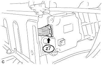
Check the connections of the z7 connector of the battery smart unit.
OK The connectors are connected securely and there are no contact problems. -
Install the No. 2 hybrid vehicle battery shield panel.
NG
CONNECT SECURELY
OK
-
-
REPLACE BATTERY SMART UNIT
NEXT
-
CLEAR DTC (HV)
-
Connect the Techstream to the DLC3.
-
Turn the power switch on (IG).
-
Enter the following menus: Powertrain / Hybrid Control / Trouble Codes.
-
Clear the DTCs and freeze frame data Click here.
-
Perform a road test to charge and discharge the HV battery.
-
Disconnect the Techstream from the DLC3.
NEXT
-
-
RECONFIRM DTC OUTPUT (HV)
-
Connect the Techstream to the DLC3.
-
Turn the power switch on (IG).
-
Enter the following menus: Powertrain / Hybrid Control / Trouble Codes.
-
Read output DTCs Click here.
Result Result Proceed to Battery temperature sensor DTCs for this diagnostic procedure are not output A Battery temperature sensor DTCs for this diagnostic procedure are output B Note
Turning the power switch on (IG) with the service grip removed causes other DTCs to be stored. Clear the DTCs after performing this inspection.
-
Turn the power switch off.
-
Disconnect the Techstream from the DLC3.
B
REPLACE HV BATTERY Click here
A 
RETURN TO NORMAL OPERATION
-