HYBRID CONTROL SYSTEM, Diagnostic DTC:P0C73-776

| DTC Code | DTC Name |
|---|---|
| P0C73-776 | Motor Electronics Coolant Pump "A" Control Performance |
DESCRIPTION
The inverter water pump assembly transmits rotation revolution information to the power management control ECU. The power management control ECU monitors the revolution and detects malfunctions.
| DTC No. | INF Code | DTC Detection Condition | Trouble Area |
|---|---|---|---|
| P0C73 | 776 | A revolution or intermittent stop malfunction occurs in the inverter water pump assembly. |
|
MONITOR DESCRIPTION
The power management control ECU monitors revolution of the inverter water pump assembly. If there is an abnormality in revolution, the power management control ECU will illuminate the MIL and set a DTC.
MONITOR STRATEGY
| Related DTCs | P0C73 (INF 776): Water pump malfunction |
| Required sensors / components | Inverter water pump assembly |
| Frequency of operation | Continuous |
| Duration | TMC's intellectual property |
| MIL operation | 1 driving cycle |
| Sequence of operation | None |
TYPICAL ENABLING CONDITIONS
| The monitor will run whenever the following DTCs are not present | TMC's intellectual property |
| Other conditions belong to TMC's intellectual property | - |
TYPICAL MALFUNCTION THRESHOLDS
| TMC's intellectual property | - |
COMPONENT OPERATING RANGE
| Power management control ECU | DTC P0C73 (INF 776) is not detected |
CONFIRMATION DRIVING PATTERN
-
Connect the Techstream to the DLC3.
-
Turn the power switch on (IG) and turn the Techstream on.
-
Clear the DTCs (even if no DTCs are stored, perform the clear DTC procedure).
-
Turn the power switch off.
-
Turn the power switch on (IG) and check that there are no abnormalities (abnormal sounds, coolant leaks, DTC output, etc).
-
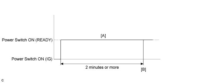
Turn the power switch on (READY) and turn the Techstream on. [A]
-
Wait for 2 minutes or more.
-
Enter the following menus: Powertrain / Hybrid Control / Trouble Codes. [B]
-
Check that permanent DTCs are cleared.
-
If the permanent DTCs are not cleared, perform a universal trip, and then check for permanent DTCs again.
Tech Tips
-
If a permanent DTC is output, the system is malfunctioning.
-
If no permanent DTC is output, the system is normal.
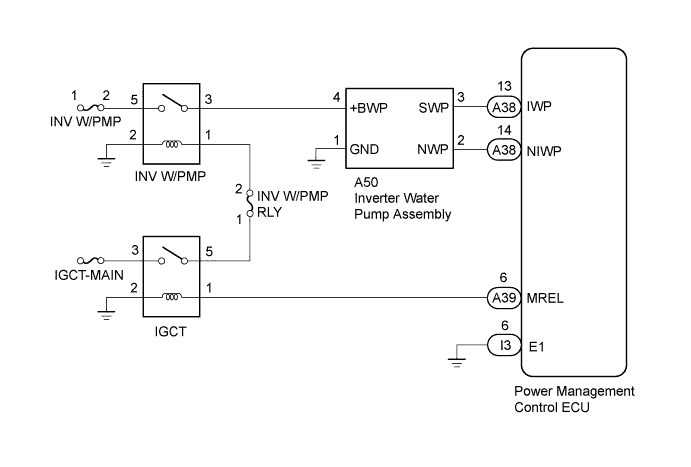
WIRING DIAGRAM
INSPECTION PROCEDURE
Note
If DTC P0A78-284, 286, P0A7A-322, 324, P0A94-553 or 557 is output, replace the inverter with converter assembly after this inspection.
PROCEDURE
-
CHECK QUANTITY OF HV COOLANT
-
Check the HV coolant level in the inverter reserve tank.
-
Check for HV coolant leaks.
Result Result Proceed to HV coolant leaks are not evident. A sufficient amount of coolant remains in the inverter reserve tank. A HV coolant leaks are not evident. No coolant remains in the inverter reserve tank. B HV coolant leaks are evident. C Tech Tips
After repairing the HV coolant leaks and adding coolant, perform the "Activate the Water Pump" Active Test (HV Active Test item) and the "Control the Electric Cooling Fan" Active Test (Engine Active Test item) and make sure that there are no malfunctions.
B 
ADD HV COOLANT Click here
C
INSPECT FOR HV COOLANT LEAK Click here
A 
-
-
CHECK COOLANT HOSE
-
Check if the hoses of the cooling system are kinked or clogged.
NG
CORRECT THE PROBLEM Click here
OK
-
-
READ VALUE USING TECHSTREAM (INVERTER W/P REVOLUTION)
Note
Be sure to perform the inspection with the auxiliary battery voltage at 11 V or more.
Tech Tips
When the auxiliary battery voltage is low, the inverter water pump assembly may not operate.
-
Connect the Techstream to the DLC3.
-
Turn the power switch on (IG).
-
Enter the following menus: Powertrain / Hybrid Control / Data List / Inverter W/P Revolution.
-
Read the Data List.
Result Tester Display Switch Condition Specified Condition Inverter W/P Revolution Power switch on (IG) 625 rpm or less -
Turn the power switch off.
NG
OK
-
-
PERFORM ACTIVE TEST USING TECHSTREAM (ACTIVATE THE WATER PUMP)
Note
Be sure to perform the inspection with the auxiliary battery voltage at 11 V or more.
Tech Tips
When the auxiliary battery voltage is low, the inverter water pump assembly may not operate.
-
Connect the Techstream to the DLC3.
-
Turn the power switch on (IG).
-
Enter the following menus: Powertrain / Hybrid Control / Active Test / Activate the Water Pump.
-
Select Inverter W/P Revolution in the Data List.
-
While performing the "Activate the Water Pump" Active Test, check Inverter W/P Revolution in the Data List.
Result Tester Display Switch Condition Specified Condition Inverter W/P Revolution Power switch on (IG) 2500 to 5875 rpm Tech Tips
Perform the Active Test with the inverter coolant temperature between -15 and 65°C (5 to 149°F).
-
Turn the power switch off.
NG
OK
-
-
CHECK HV COOLANT (CHECK FOR CONDITIONS THAT MAY HAVE CAUSED FREEZING)
-
Connect the Techstream to the DLC3.
-
Turn the power switch on (IG).
-
Enter the following menus: Powertrain / Hybrid Control / Trouble Codes.
-
Read the freeze frame data Ambient Temperature using the Techstream.
-
Check if the freeze frame data Ambient Temperature is below freezing.
Result Result Proceed to Ambient Temperature value is above freezing temperature of the HV coolant. A Ambient Temperature value is below freezing temperature of the HV coolant. B Tech Tips
-
HV coolant (SLLC) with a 30% concentration freezes at -15 °C (5°F) and HV coolant (SLLC) with a 50% concentration freezes at -35°C (-31°F).
-
If the HV coolant freezes in the HV radiator or HV water pump, the coolant temperature in the inverter with converter assembly rises because the HV coolant cannot circulate. As a result, a DTC may be set.
-
A DTC is set when the water pump impeller cannot rotate due to freezing of the HV coolant.
-
If a DTC is set due to freezing of HV coolant, the problem cannot be reproduced. Judge whether freezing of HV coolant occurred according to the freeze point of the HV coolant, HV coolant change history and ambient temperature when the DTC was set.
-
-
Turn the power switch off.
B
A 
REPLACE INVERTER WATER PUMP ASSEMBLY Click here
-
-
ADD HV COOLANT
-
Add HV coolant up to the high level in the reserve tank.
NEXT
-
-
INSPECT FOR HV COOLANT LEAK
-
Diagnose and repair the HV coolant leak.
NEXT
-
-
CORRECT THE PROBLEM
-
Correct the coolant hose.
NEXT
-
-
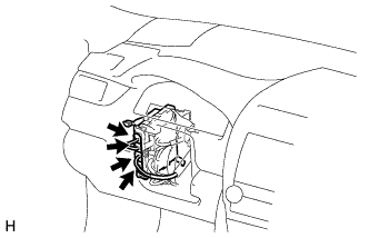
CHECK CONNECTOR CONNECTION CONDITION (POWER MANAGEMENT CONTROL ECU CONNECTOR)
-
Check the connector connections and contact pressure of the relevant terminals for the power management control ECU connectors Click here.
OK The connectors are connected securely and there are no contact pressure problems.
NG
CONNECT SECURELY Click here
OK
-
-
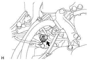
CHECK CONNECTOR CONNECTION CONDITION (INVERTER WATER PUMP ASSEMBLY CONNECTOR)
-
Check the connector connections and contact pressure of the relevant terminals for the inverter water pump assembly connector Click here.
OK The connectors are connected securely and there are no contact pressure problems.
NG
CONNECT SECURELY Click here
OK
-
-
CHECK HARNESS AND CONNECTOR (POWER MANAGEMENT CONTROL ECU - INVERTER WATER PUMP ASSEMBLY)
-
Disconnect connector A38 from the power management control ECU.
-
Disconnect connector A50 from the inverter water pump assembly.
-
Measure the resistance according to the value(s) in the table below.
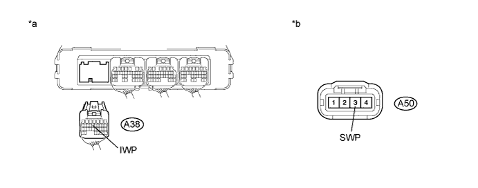
Text in Illustration *a Rear view of wire harness connector
(to Power Management Control ECU)
*b Front view of wire harness connector
(to Inverter Water Pump Assembly)
Standard Resistance (Check for Open) Tester Connection Switch Condition Specified Condition A50-3 (SWP) - A38-13 (IWP) Power switch off Below 1 Ω Standard Resistance (Check for Short) Tester Connection Switch Condition Specified Condition A50-3 (SWP) or A38-13 (IWP) - Body ground and other terminals Power switch off 10 kΩ or higher -
Connect the power management control ECU connector.
-
Connect the inverter water pump assembly connector.
NG
REPAIR OR REPLACE HARNESS OR CONNECTOR Click here
OK
-
-
READ VALUE USING TECHSTREAM (INVERTER W/P REVOLUTION)
Note
Be sure to perform the inspection with the auxiliary battery voltage at 11 V or more.
Tech Tips
When the auxiliary battery voltage is low, the inverter water pump assembly may not operate.
-
Connect the Techstream to the DLC3.
-
Disconnect connector A50 from the inverter water pump assembly.
-
Turn the power switch on (IG).
-
Enter the following menus: Powertrain / Hybrid Control / ECU Data List / Inverter W/P Revolution.
-
Read the Data List.
Result Tester Display Switch Condition Specified Condition Inverter W/P Revolution Power switch on (IG) 125 rpm or less -
Connect the inverter water pump assembly connector.
-
Turn the power switch off.
NG
REPLACE POWER MANAGEMENT CONTROL ECU Click here
OK
-
-
CHECK HARNESS AND CONNECTOR (POWER MANAGEMENT CONTROL ECU - INVERTER WATER PUMP ASSEMBLY)
-
Disconnect connector A38 from the power management control ECU.
-
Turn the power switch on (IG).
-
Measure the voltage according to the value(s) in the table below.
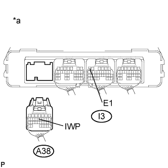
Standard Voltage Tester Connection Switch Condition Specified Condition A38-13 (IWP) - I3-6 (E1) Power switch on (IG) 11 to 14 V Text in Illustration *a Rear view of wire harness connector
(to Power Management Control ECU)
Note
Turning the power switch on (IG) with the power management control ECU connector disconnected causes other DTCs to be stored. Clear the DTCs after performing this inspection.
-
Turn the power switch off.
-
Connect the power management control ECU connector.
NG 
REPLACE INVERTER WATER PUMP ASSEMBLY Click here
OK
-
-
CHECK POWER MANAGEMENT CONTROL ECU (CHECK WAVEFORM)
-
Turn the power switch on (IG).
-
While turning the power switch on (IG), check the waveform between the power management control ECU terminals.
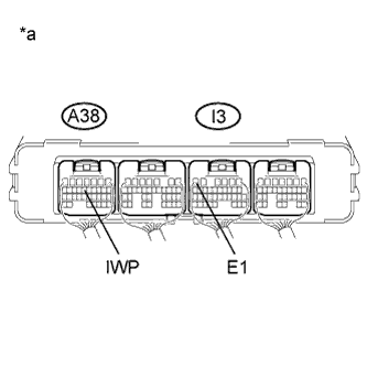
Item Content Terminal A38-13 (IWP) - I3-6 (E1) Equipment Setting 5 V/DIV., 50 ms./DIV. Condition Power switch on (IG) Text in Illustration *a Component with Harness Connected
(Power Management Control ECU)
OK Waveform duty ratio is between 3% and 9%. -
Turn the power switch off.
NG
REPLACE POWER MANAGEMENT CONTROL ECU Click here
OK
REPLACE INVERTER WATER PUMP ASSEMBLY Click here
-
-
CONNECT SECURELY
-
Connect the power management control ECU connectors securely.
NEXT
-
-
CONNECT SECURELY
-
Connect the inverter water pump assembly connector securely.
NEXT
-
-
REPLACE POWER MANAGEMENT CONTROL ECU
NEXT
-
REPLACE POWER MANAGEMENT CONTROL ECU
NEXT
-
REPLACE HV COOLANT
-
Replace the HV coolant with coolant having an appropriate concentration (appropriate freeze point) for the vehicle usage conditions Click here.
NEXT
-
-
CHECK INVERTER WATER PUMP ASSEMBLY
-
Perform a road test and check that DTCs are not stored.
CAUTION:
Perform this road test only in an appropriate safe location, in accordance with all local laws.
OK DTCs are not stored.
NG
REPLACE INVERTER WATER PUMP ASSEMBLY Click here
OK
COMPLETED
-