HYBRID CONTROL SYSTEM, Diagnostic DTC:P0A93-346

| DTC Code | DTC Name |
|---|---|
| P0A93-346 | Inverter Cooling System Performance |
DESCRIPTION
The inverter converts the high-voltage direct current of the HV battery into the alternating current for MG1 and MG2. The inverter generates heat during the conversion process. Therefore, the inverter is cooled by a special cooling system consisting of the inverter water pump assembly, the cooling fan, and a radiator. This cooling system is independent of the engine cooling system. The power management control ECU monitors the inverter water pump assembly, cooling fan, and cooling system, and detects the following malfunctions.
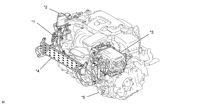
| *1 | Inverter Water Pump Assembly | *2 | Inverter Reserve Tank Assembly |
| *3 | Inverter with Converter Assembly | *4 | Radiator Assembly (HV) |
| *5 | Hybrid Vehicle Transaxle Assembly | - | - |
| DTC No. | INF Code | DTC Detection Condition | Trouble Area |
|---|---|---|---|
| P0A93 | 346 | Inverter cooling system malfunction (HV cooling malfunction) |
|
MONITOR DESCRIPTION
If the power management control ECU detects a malfunction of the inverter water pump assembly, fan or radiator, the ECU will illuminate the MIL and set a DTC.
MONITOR STRATEGY
| Related DTCs | P0A93 (INF 346): HV cooling system malfunction |
| Required sensors / components | Inverter water pump assembly |
| Frequency of operation | Continuous |
| Duration | TMC's intellectual property |
| MIL operation | 1 driving cycle |
| Sequence of operation | None |
TYPICAL ENABLING CONDITIONS
| The monitor will run whenever the following DTCs are not present | TMC's intellectual property |
| Other conditions belong to TMC's intellectual property | - |
TYPICAL MALFUNCTION THRESHOLDS
| TMC's intellectual property | - |
COMPONENT OPERATING RANGE
| Power management control ECU | DTC P0A93 (INF 346) is not detected |
CONFIRMATION DRIVING PATTERN
-
Connect the Techstream to the DLC3.
-
Turn the power switch on (IG) and turn the Techstream on.
-
Clear the DTCs (even if no DTCs are stored, perform the clear DTC procedure).
-
Turn the power switch off.
-
Turn the power switch on (IG) and check that there are no abnormalities (abnormal sounds, coolant leaks, DTC output, etc).
-
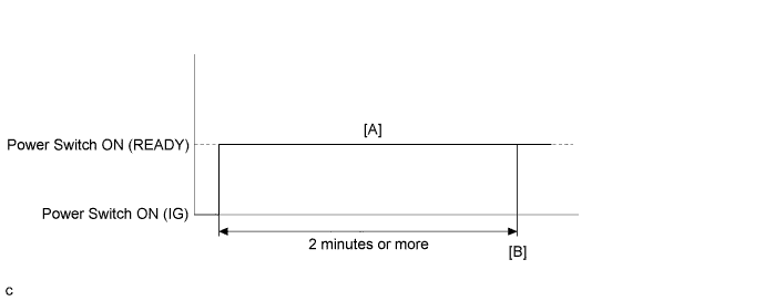
Turn the power switch on (READY) and turn the Techstream on. [A]
-
Wait for 2 minutes or more.
-
Enter the following menus: Powertrain / Hybrid Control / Trouble Codes. [B]
-
Check that permanent DTCs are cleared.
-
If the permanent DTCs are not cleared, perform a universal trip, and then check for permanent DTCs again.
Tech Tips
-
If a permanent DTC is output, the system is malfunctioning.
-
If no permanent DTC is output, the system is normal.
INSPECTION PROCEDURE
CAUTION:
-
Before inspecting the high-voltage system or disconnecting the low voltage connector of the inverter with converter assembly, take safety precautions such as wearing insulated gloves and removing the service plug grip to prevent electrical shocks. After removing the service plug grip, put it in your pocket to prevent other technicians from accidentally reconnecting it while you are working on the high-voltage system.
-
After removing the service plug grip, wait for at least 10 minutes before touching any of the high-voltage connectors or terminals. After waiting for 10 minutes, check the voltage at the terminals in the inspection point in the inverter with converter assembly. The voltage should be 0 V before beginning work Click here.
Tech Tips
Waiting for at least 10 minutes is required to discharge the high-voltage capacitor inside the inverter with converter assembly.
Note
-
After turning the power switch off, waiting time may be required before disconnecting the cable from the negative (-) auxiliary battery terminal. Therefore, make sure to read the disconnecting the cable from the negative (-) auxiliary battery terminal notices before proceeding with work Click here.
-
If DTC P0A78-284, 286, P0A7A-322, 324, P0A94-553 or 557 is output, replace the inverter with converter assembly after this inspection.
PROCEDURE
-
CHECK DTC OUTPUT (HYBRID CONTROL)
-
Connect the Techstream to the DLC3.
-
Turn the power switch on (IG).
-
Enter the following menus: Powertrain / Hybrid Control / Trouble Codes.
-
Check if DTCs are output.
Result Result Proceed to P0A93-346 only is output. A Any of the following DTCs are also output. B DTC No. Relevant Diagnosis P0A02-719 Motor Electronics Coolant Temperature Sensor Circuit Low P0A03-720 Motor Electronics Coolant Temperature Sensor Circuit High P0C73-776 Motor Electronics Coolant Pump "A" Control Performance P314A-828 Inverter Coolant Pump Speed Signal Tech Tips
P0A93-346 may be set due to a malfunction which also causes DTCs in the preceding table to be set. In this case, first troubleshoot the output DTCs in the preceding table. Then, perform a test to attempt to reproduce the problems, and check that no DTCs are output.
-
Turn the power switch off.
B 
GO TO DTC CHART (HYBRID CONTROL SYSTEM) Click here
A 
-
-
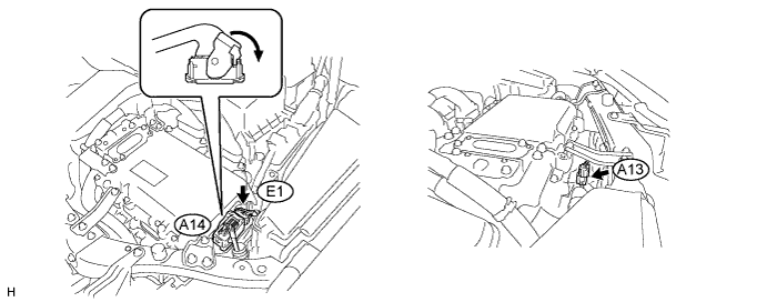
CHECK CONNECTOR CONNECTION CONDITION (INVERTER WITH CONVERTER ASSEMBLY CONNECTOR)
CAUTION:
Be sure to wear insulated gloves.
-
Check that the service plug grip is not installed.
Note
After removing the service plug grip, do not turn the power switch on (READY), unless instructed by the repair manual because this may cause a malfunction.
-
Check the connector connections and contact pressure of the low voltage connectors of the inverter with converter assembly Click here.
Note
Before disconnecting the connector, confirm that it is properly connected by checking that the locking claws are engaged and that the connector does not pull out.
OK The connectors are connected securely and there are no contact pressure problems. Tech Tips
When connecting the connector, insert it with the locking lever in the raised position. Rotate the lever downward and make sure that the connector is pulled into its socket. When the locking lever is in its fully closed position, a click will be heard as its locking claws engage. After the click is heard, pull up on the connector to confirm that it is properly connected.
NG
CONNECT SECURELY
OK
-
-
CHECK QUANTITY OF HV COOLANT
-
Check the HV coolant level in the inverter reserve tank.
-
Check for HV coolant leaks.
Result Result Proceed to HV coolant leaks are not evident. A sufficient amount of coolant remains in the inverter reserve tank. A HV coolant leaks are not evident. No coolant remains in the inverter reserve tank. B HV coolant leaks are evident. C Tech Tips
After repairing the HV coolant leaks and adding coolant, perform the "Activate the Water Pump" Active Test (HV Active Test item) and the "Control the Electric Cooling Fan" Active Test (Engine Active Test item) and make sure that there are no malfunctions.
B
ADD HV COOLANT
C
INSPECT FOR HV COOLANT LEAK AND ADD HV COOLANT
A
-
-
CHECK COOLANT HOSE
-
Check if the hoses of the cooling system are kinked or clogged.
NG
CORRECT THE PROBLEM
OK
-
-
PERFORM ACTIVE TEST USING TECHSTREAM (CONTROL THE ELECTRIC COOLING FAN)
-
Connect the Techstream to the DLC3.
-
Turn the power switch on (IG).
-
Enter the following menus: Powertrain / Engine and ECT / Active Test / Control the Electric Cooling Fan.
-
Perform the "Control the Electric Cooling Fan" Active Test.
OK The cooling fan rotates. -
Turn the power switch off.
NG
CHECK COOLING FAN SYSTEM Click here
OK
-
-
READ VALUE USING TECHSTREAM (DATA LIST)
-
Turn the power switch off and leave the vehicle for at least 1 hour.
-
Connect the Techstream to the DLC3.
-
Turn the power switch on (IG).
-
Enter the following menus: Powertrain / Hybrid Control / Data List / Inverter Coolant Water Temperature, Inverter Temp (MG2), Cnv Tmp (Upper), Cnv Temp (Lower), Inverter Temp (MG1).
-
Read the Data List.
Result Result Proceed to The difference between "Inverter Coolant Water Temperature" value and other temperatures selected in the list is smaller than 20°C (36°F). A The difference between "Inverter Coolant Water Temperature" value and other temperatures selected in the list is 20°C (36°F) or more. B Note
The lower limit temperature that can be displayed for "Inverter Temp (MG1)", "Inverter Temp (MG2)", "Cnv Tmp (Upper)" and "Cnv Temp (Lower)" is 15°C (59°F). The lower limit temperature for "Inverter Coolant Water Temperature" is -40°C (-40°F). The "Inverter Coolant Water Temperature" value displayed on the Techstream may be lower than the others, but this is not a malfunction.
-
Turn the power switch off.
B
REPLACE INVERTER WITH CONVERTER ASSEMBLY Click here
A
-
-
CHECK HV COOLANT (CHECK FOR CONDITIONS THAT MAY HAVE CAUSED FREEZING)
-
Connect the Techstream to the DLC3.
-
Turn the power switch on (IG).
-
Enter the following menus: Powertrain / Hybrid Control / Trouble Codes.
-
Read the freeze frame data Ambient Temperature using the Techstream.
-
Check if the freeze frame data Ambient Temperature is below freezing.
Result Result Proceed to Ambient Temperature value is below freezing temperature of the HV coolant. A Ambient Temperature value is above freezing temperature of the HV coolant. B Tech Tips
-
HV coolant (SLLC) with a 30% concentration freezes at -15 °C (5°F) and HV coolant (SLLC) with a 50% concentration freezes at -35°C (-31°F).
-
If the HV coolant freezes in the HV radiator or HV water pump, the coolant temperature in the inverter with converter assembly rises because the HV coolant cannot circulate. As a result, a DTC may be set.
-
A DTC is set when the water pump impeller cannot rotate due to freezing of the HV coolant.
-
If a DTC is set due to freezing of HV coolant, the problem cannot be reproduced. Judge whether freezing of HV coolant occurred according to the freeze point of the HV coolant, HV coolant change history and ambient temperature when the DTC was set.
-
-
Turn the power switch off.
B
REPLACE INVERTER WATER PUMP ASSEMBLY Click here
A
-
-
REPLACE HV COOLANT
-
Replace the HV coolant with coolant having an appropriate concentration (appropriate freeze point) for the vehicle usage conditions Click here.
NEXT
-
-
CHECK INVERTER WATER PUMP ASSEMBLY
-
Perform a road test and check that DTCs are not stored.
CAUTION:
Perform this road test only in an appropriate safe location, in accordance with all local laws.
OK DTCs are not stored.
NG
REPLACE INVERTER WATER PUMP ASSEMBLY Click here
OK 
COMPLETED
-