HYBRID CONTROL SYSTEM, Diagnostic DTC:P0A1B-163, P0A1B-164, P0A1B-192, P0A1B-193, P0A1B-511, P0A1B-512, P0A1B-661, P0A1B-786, P0A1B-794

| DTC Code | DTC Name |
|---|---|
| P0A1B-163 | Drive Motor "A" Control Module |
| P0A1B-164 | Drive Motor "A" Control Module |
| P0A1B-192 | Drive Motor "A" Control Module |
| P0A1B-193 | Drive Motor "A" Control Module |
| P0A1B-511 | Drive Motor "A" Control Module |
| P0A1B-512 | Drive Motor "A" Control Module |
| P0A1B-661 | Drive Motor "A" Control Module |
| P0A1B-786 | Drive Motor "A" Control Module |
| P0A1B-794 | Drive Motor "A" Control Module |
DESCRIPTION
The MG ECU located in the inverter with converter assembly monitors its internal operation and it will set DTCs when it detects malfunctions. If any of the following DTCs are output, replace the inverter with converter assembly.
Tech Tips
The term "drive motor A" indicates MG2.
| DTC No. | INF Code | DTC Detection Condition | Trouble Area |
|---|---|---|---|
| P0A1B | 163 | IPM positive power source error | Inverter with converter assembly |
| 164 | IPM negative power source error | ||
| 192 | A/D converter error | ||
| 193 | CPU ROM-RAM error | ||
| 511 | Standard voltage for analog signal offset | ||
| 512 | Standard voltage for analog signal error | ||
| 661 | Communication error (from MG2 to MG1) | ||
| 786 | ALU error | ||
| 794 | R/D converter communication error |
MONITOR DESCRIPTION
The MG ECU (in the inverter with converter assembly) performs many diagnostic tests to verify proper operation of internal ECU systems. In one of those tests, the MG ECU checks the result of the motor CPU self-test. If the MG ECU detects a "Fail" from the motor CPU self-test, it will conclude that there is an internal malfunction in the motor CPU. The power management control ECU will illuminate the MIL and set a DTC.
MONITOR STRATEGY
| Related DTCs | P0A1B (INF 163): Motor CPU power malfunction (26 V) P0A1B (INF 164): Motor CPU power malfunction (-5 V) P0A1B (INF 192): A/D malfunction (2 MG CPU) P0A1B (INF 193): RAM and ROM destruction P0A1B (INF 511): Motor CPU power malfunction (2.5 V) P0A1B (INF 512): Motor CPU power malfunction (5 Aref) P0A1B (INF 661): 2 MG CPU communication malfunction (2 MG CPU to 1 MG CPU) P0A1B (INF 786): MG CPU ALU malfunction P0A1B (INF 794): R/D converter communication malfunction |
| Required sensors / components | Inverter with converter (MG ECU) |
| Frequency of operation | Continuous |
| Duration | TMC's intellectual property |
| MIL operation | 1 driving cycle: P0A1B-163, 164, 192, 193, 511, 512, 661, 794 Immediately: P0A1B-786 |
| Sequence of operation | None |
TYPICAL ENABLING CONDITIONS
| The monitor will run whenever the following DTCs are not present | TMC's intellectual property |
| Other conditions belong to TMC's intellectual property | - |
TYPICAL MALFUNCTION THRESHOLDS
| TMC's intellectual property | - |
COMPONENT OPERATING RANGE
| Power management control ECU | DTC P0A1B (INF 163/164/192/193/511/512/661/786/794) is not detected |
CONFIRMATION DRIVING PATTERN
-
Connect the Techstream to the DLC3.
-
Turn the power switch on (IG) and turn the Techstream on.
-
Clear the DTCs (even if no DTCs are stored, perform the clear DTC procedure).
-
Turn the power switch off.
-
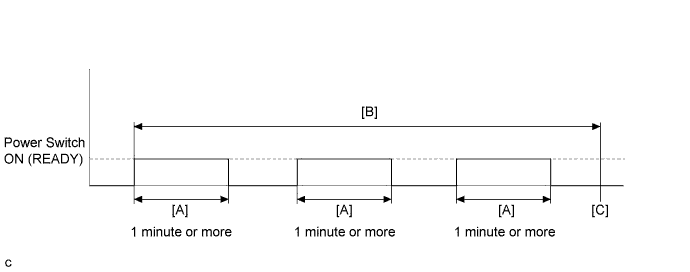
Turn the power switch on (READY) and after 1 minute or more, turn the power switch off. [A]
-
Repeat [A] 3 times. [B]
-
Turn the power switch on (IG) and turn the Techstream on.
-
Enter the following menus: Powertrain / Hybrid Control / Trouble Codes. [C]
-
Check that permanent DTCs are cleared.
-
If the permanent DTCs are not cleared, perform the universal trip, and then check for permanent DTCs again.
Tech Tips
-
If a permanent DTC is output, the system is malfunctioning.
-
If no permanent DTC is output, the system is normal.
INSPECTION PROCEDURE
PROCEDURE
-
REPLACE INVERTER WITH CONVERTER ASSEMBLY
NEXT 
COMPLETED