HYBRID CONTROL SYSTEM, Diagnostic DTC:P0A94-442

| DTC Code | DTC Name |
|---|---|
| P0A94-442 | DC / DC Converter Performance |
DESCRIPTION
The boost converter boosts the 244.8 V DC from the HV battery to a maximum of approximately 650 V DC. The inverter converts the voltage that has been boosted by the boost converter into alternating current, which is used for driving MG1 and MG2. When a motor generator operates as a generator, the alternating current that it creates is converted into direct current by the inverter. Then the boost converter drops this voltage to direct-current of approximately 244.8 V in order to charge the HV battery.
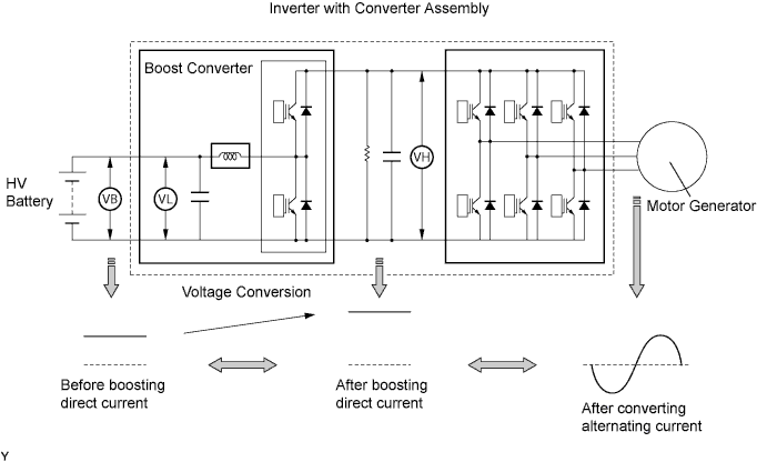
The MG ECU uses a voltage sensor (VL) that is built into the boost converter to detect the high voltage before it is boosted. It also uses a voltage sensor (VH) that is built into the inverter to detect the high voltage after it is boosted. Based on the voltage before and after it is boosted, the MG ECU controls the operation of the boost converter to boost the voltage to the target voltage.
| DTC No. | INF Code | DTC Detection Condition | Trouble Area |
|---|---|---|---|
| P0A94 | 442 | Abnormal voltage execution value | Inverter with converter assembly |
MONITOR DESCRIPTION
If the difference between the requested boost converter voltage and the actual boost converter voltage exceeds a predetermined value, the MG ECU determines that there is a malfunction of the execution or monitoring in the boost converter voltage. The MG ECU will send information about the malfunction to the power management control ECU. Upon receiving this information, the power management control ECU will illuminate the MIL and set a DTC.
MONITOR STRATEGY
| Related DTCs | P0A94 (INF 442): Discrepancy between commanded and actual voltage |
| Required sensors / components | Boost converter |
| Frequency of operation | Continuous |
| Duration | TMC's intellectual property |
| MIL operation | 1 driving cycle |
| Sequence of operation | None |
TYPICAL ENABLING CONDITIONS
| The monitor will run whenever the following DTCs are not present | TMC's intellectual property |
| Other conditions belong to TMC's intellectual property | - |
TYPICAL MALFUNCTION THRESHOLDS
| TMC's intellectual property | - |
COMPONENT OPERATING RANGE
| Power management control ECU | DTC P0A94 (INF 442) is not detected |
CONFIRMATION DRIVING PATTERN
-
Connect the Techstream to the DLC3.
-
Turn the power switch on (IG) and turn the Techstream on.
-
Clear the DTCs (even if no DTCs are stored, perform the clear DTC procedure).
-
Turn the power switch off.
-
Turn the power switch on (READY) and turn the Techstream on.
-
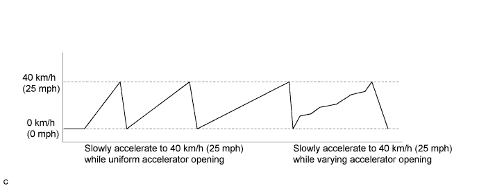
Slowly accelerate from a stop (0 km/h (0 mph)) to 40 km/h (25 mph) several times while using different acceleration patterns.
Tech Tips
The vehicle should be driven with an accelerator opening of approximately 50%.
-
Enter the following menus: Powertrain / Hybrid Control / Trouble Codes.
-
Check that permanent DTCs are cleared.
-
If the permanent DTCs are not cleared, perform a universal trip, and then check for permanent DTCs again.
Tech Tips
-
If a permanent DTC is output, the system is malfunctioning.
-
If no permanent DTC is output, the system is normal.
INSPECTION PROCEDURE
CAUTION:
-
Before inspecting the high-voltage system or disconnecting the low voltage connector of the inverter with converter assembly, take safety precautions such as wearing insulated gloves and removing the service plug grip to prevent electrical shocks. After removing the service plug grip, put it in your pocket to prevent other technicians from accidentally reconnecting it while you are working on the high-voltage system.
-
After removing the service plug grip, wait for at least 10 minutes before touching any of the high-voltage connectors or terminals. After waiting for 10 minutes, check the voltage at the terminals in the inspection point in the inverter with converter assembly. The voltage should be 0 V before beginning work Click here.
Tech Tips
Waiting for at least 10 minutes is required to discharge the high-voltage capacitor inside the inverter with converter assembly.
Note
After turning the power switch off, waiting time may be required before disconnecting the cable from the negative (-) auxiliary battery terminal. Therefore, make sure to read the disconnecting the cable from the negative (-) auxiliary battery terminal notices before proceeding with work Click here.
PROCEDURE
-
CHECK DTC OUTPUT (HYBRID CONTROL)
-
Connect the Techstream to the DLC3.
-
Turn the power switch on (IG).
-
Enter the following menus: Powertrain / Hybrid Control / Trouble Codes.
-
Check if DTCs are output.
Result Result Proceed to P0A94-442 only is output. A Any of the following DTCs are also output. B DTC No. Relevant Diagnosis P0A1A (all INF codes)*1 Generator Control Module P0A1B (all INF codes)*1 Drive Motor "A" Control Module P0A1D (all INF codes)*1 Hybrid Powertrain Control Module P0A3F-243 Drive Motor "A" Position Sensor Circuit P0A40-500 Drive Motor "A" Position Sensor Circuit Range / Performance P0A41-245 Drive Motor "A" Position Sensor Circuit Low P0A4B-253 Generator Position Sensor Circuit P0A4C-513 Generator Position Sensor Circuit Range / Performance P0A4D-255 Generator Position Sensor Circuit Low P0A60 (all INF codes)*1 Drive Motor "A" Phase V Current P0A63 (all INF codes)*1 Drive Motor "A" Phase W Current P0A72 (all INF codes)*1 Generator Phase V Current P0A75 (all INF codes)*1 Generator Phase W Current P0A78-266, 267, 279, 287, 503, 504, 505, 506, 586, 806, 807, 808 Drive Motor "A" Inverter Performance P0A7A-325, 517, 518, 809, 810, 811 Generator Inverter Performance P0A90-509 Drive Motor "A" Performance P0A92-521 Hybrid Generator Performance P0A94-547, 548, 549, 554, 555, 556, 585, 587, 589, 590 DC / DC Converter Performance P0C76-523 Hybrid Battery System Discharge Time Too Long Tech Tips
-
*1: If any INF codes are output for this DTC, refer to the corresponding diagnostic procedure.
-
P0A94-442 may be set due to a malfunction which also causes DTCs in the preceding table to be set. In this case, first troubleshoot the output DTCs in the preceding table. Then, perform a test to attempt to reproduce the problems, and check that no DTCs are output.
-
-
Turn the power switch off.
B 
GO TO DTC CHART (HYBRID CONTROL SYSTEM) Click here
A 
-
-
CHECK CONNECTOR CONNECTION CONDITION (INVERTER WITH CONVERTER ASSEMBLY CONNECTOR)
CAUTION:
Be sure to wear insulated gloves.
-
Check that the service plug grip is not installed.
Note
After removing the service plug grip, do not turn the power switch on (READY), unless instructed by the repair manual because this may cause a malfunction.
-
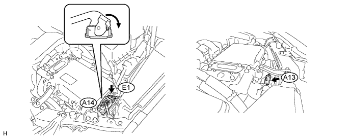
Check the connector connections and contact pressure of the low voltage connectors of the inverter with converter assembly Click here.
Note
Before disconnecting the connector, confirm that it is properly connected by checking that the locking claws are engaged and that the connector does not pull out.
OK The connectors are connected securely and there are no contact pressure problems. Tech Tips
When connecting the connector, insert it with the locking lever in the raised position. Rotate the lever downward and make sure that the connector is pulled into its socket. When the locking lever is in its fully closed position, a click will be heard as its locking claws engage. After the click is heard, pull up on the connector to confirm that it is properly connected.
NG
CONNECT SECURELY
OK 
REPLACE INVERTER WITH CONVERTER ASSEMBLY Click here
-