THROTTLE BODY INSTALLATION

-
INSTALL THROTTLE WITH MOTOR BODY ASSEMBLY
-
Install a new gasket to the intake manifold.
-
Install the throttle with motor body assembly with the 4 bolts.
- Torque:
- 10 N*m { 102 kgf*cm, 7 ft.*lbf }
-
Connect the throttle body connector.
-
Connect the 2 water by-pass hoses to the throttle with motor body assembly.
-
Connect the 2 hoses.
-
-
INSTALL AIR CLEANER CAP SUB-ASSEMBLY
-
Install the air cleaner hose with the hose clamp.
-
Connect the 2 fuel vapor feed hoses.
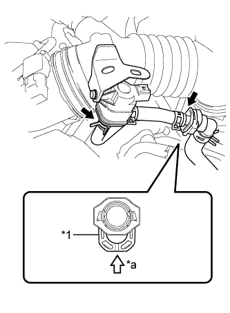
Text in Illustration *1 Retainer *a Push Note
-
Check that there are no scratches or foreign matter around the connected part of the fuel tube connector and pipe before performing this work.
-
Connect the quick connector and push the retainer in until the retainer makes a "click" sound to lock the claws of the retainer.
-
After connecting the fuel vapor feed hose to the fuel tube connector, check that the fuel vapor feed hose is securely connected by pulling on the fuel tube connector and the fuel vapor feed hose.
-
-
Connect the 2 hinges of the air cleaner cap subassembly.
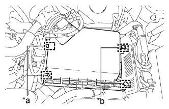
Text in Illustration *a Hinge *b Clamp -
Install the air cleaner cap sub-assembly with the 2 clamps.
-
Connect the wire harness clamp and connector.
-
Connect the ventilation hose to the cylinder head cover.
-
Connect the mass air flow meter connector and wire harness clamp to the air cleaner cap sub-assembly.
-
-
ADD COOLANT (for Engine)
-
Tighten the radiator drain cock plug by hand.
-
Slowly fill the radiator with TOYOTA Super Long Life Coolant (SLLC).
Item Capacity Engine coolant 7.2 liters (7.6 US qts, 6.3 Imp. qts) Note
Never use water as a substitute for engine coolant.
Tech Tips
TOYOTA vehicles are filled with TOYOTA SLLC at the factory. In order to avoid damage to the engine cooling system and other technical problems, only use TOYOTA SLLC or similar high quality ethylene glycol based non-silicate, non-amine, non-nitrite, non-borate coolant with long-life hybrid organic acid technology (coolant with long-life hybrid organic acid technology is a combination of low phosphates and organic acids).
-
Slowly pour coolant into the radiator reserve tank assembly until it reaches the full line.
-
Squeeze the No. 1 and No. 2 radiator hoses several times by hand, and then check the level of the coolant.
If the coolant level is low, add coolant.
-
Install the radiator cap sub-assembly and reserve tank cap.
-
Put the engine in inspection mode Click here.
-
Bleed air from the cooling system.
Note
-
Before starting the engine, turn the A/C switch off.
-
Adjust the heater control to the maximum hot setting.
-
Adjust the blower speed to the low setting.
-
Warm up the engine until the thermostat opens. While the thermostat is open, circulate the coolant for several minutes.
Tech Tips
The thermostat open timing can be confirmed by squeezing the No. 2 radiator hose by hand, and sensing vibrations when the engine coolant starts to flow inside the hose.
-
Squeeze the No. 1 and No. 2 radiator hoses several times by hand to bleed air.
CAUTION:
When squeezing the radiator hoses:
-
Wear protective gloves.
-
Be careful as the radiator hoses are hot.
-
Keep your hands away from the cooling fans.
Note
-
Make sure that the radiator reserve tank assembly still has some coolant in it.
-
If the coolant temperature gauge indicates an excessive temperature, turn off the engine and let it cool.
-
If there is not enough coolant, the engine may overheat or be seriously damaged.
-
If the radiator reserve tank assembly does not have enough coolant, perform the following: 1) stop the engine, 2) wait until the coolant has cooled down, and 3) add coolant until the reserve tank assembly is filled to the full line.
-
-
-
Stop the engine and wait until the engine coolant cools down.
-
Add engine coolant to the full line on the radiator reserve tank assembly.
-
-
INSPECT FOR COOLANT LEAK (for Engine)
Note
Before performing each inspection, turn the A/C switch off.
-
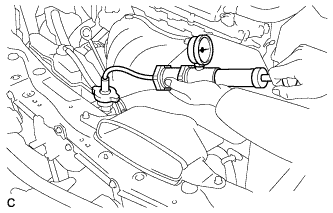
Fill the radiator with coolant and attach a radiator cap tester.
-
Put the engine in inspection mode Click here.
-
Warm up the engine.
-
Using a radiator cap tester, increase the pressure inside the radiator to 118 kPa (1.2 kgf/cm2, 17 psi), and check that the pressure does not drop.
If the pressure drops, check the hoses, radiator and water pump for leaks. If no external leaks are found, check the heater core, cylinder block and cylinder head.
-
-
INSTALL NO. 1 ENGINE COVER SUB-ASSEMBLY
-
Engage the 3 pins and install the No. 1 engine cover sub-assembly.
-
-
PERFORM INITIALIZATION
Note
-
Be sure to perform this procedure after reassembling the throttle with motor body assembly or removing and reinstalling any throttle body components.
-
Perform the following procedure after replacing the throttle with motor body assembly or any throttle body components. The following procedure should also be performed if the throttle body is cleaned.
-
Turn the power switch on (IG) without operating the accelerator pedal.
Note
If the accelerator pedal is operated, perform the above step again.
-
Connect the tester to the DLC3 and clear the DTCs Click here.
-
Perform the "Inspection After Repair" Click here.
-
Start the engine and check that the MIL is not illuminated. After the engine is warmed up, check that the idle speed is within the specified range when the A/C is switched off.
Standard Condition Engine Idle Speed A/C switched off 900 to 1050 rpm Note
-
Be sure to perform this step with all accessories off.
-
Make sure that the shift lever is in N.
-
-
Enter the following menus: Powertrain / Engine and ECT / Data List / All Data /Throttle Sensor Position. Fully depress the accelerator pedal and check that the value is 60% or more.
-
Perform a road test and confirm that there are no abnormalities.
-