SLIDING ROOF HOUSING INSTALLATION

-
INSTALL SLIDING ROOF HOUSING SUB-ASSEMBLY
-
Tighten the 8 bolts of the brackets.
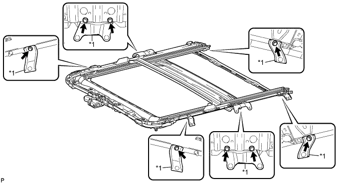
Text in Illustration *1 Bracket - - - Torque:
- 8.0 N*m { 82 kgf*cm, 71 in.*lbf }
-
Loosen the 8 bolts of the brackets a half turn.
Note
Make sure to loosen the 8 bolts of the brackets before installing the sliding roof housing sub-assembly as excessive force may be applied to the sliding roof housing sub-assembly when installing it.
-
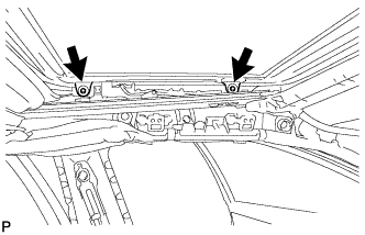
Temporarily install the sliding roof housing sub-assembly with the 8 nuts and 8 bolts.
-
Tighten the 8 nuts and 8 bolts in the order shown in the illustration to install the sliding roof housing sub-assembly.
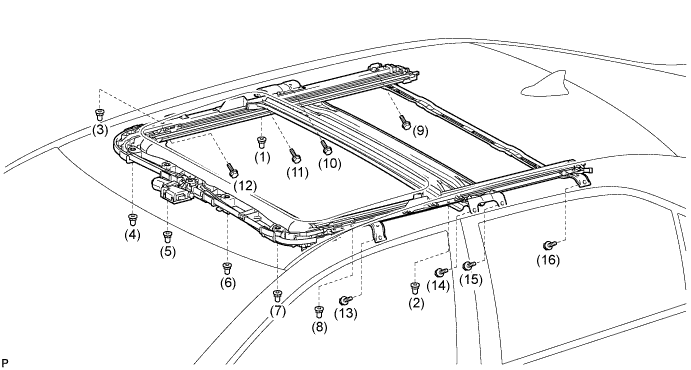
- Torque:
- Nut
- 5.5 N*m { 56 kgf*cm, 49 in.*lbf }
- Bolt
- 8.0 N*m { 82 kgf*cm, 71 in.*lbf }
-
Tighten the 8 bolts of the brackets in the order shown in the illustration.
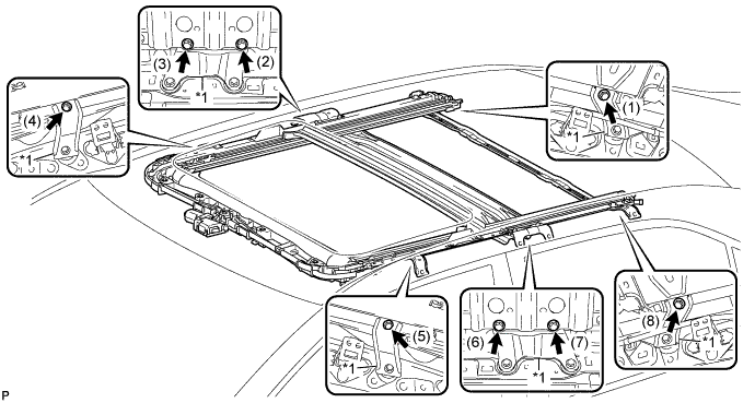
Text in Illustration *1 Bracket - - - Torque:
- 8.0 N*m { 82 kgf*cm, 71 in.*lbf }
-
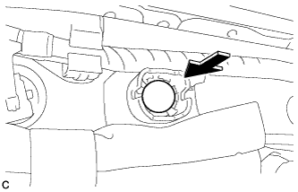
for Clamp Type:
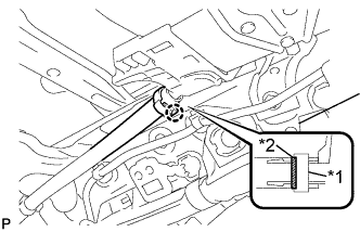
Text in Illustration *1 Clamp *2 Marking -
Insert the sliding roof drain hose.
Tech Tips
The hose should be inserted to the base of the drain pipe.
-
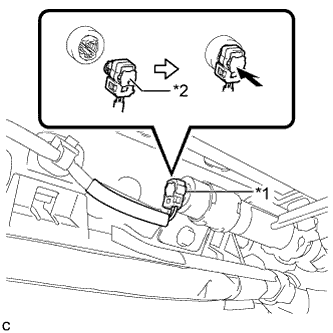
Engage the claw to connect the sliding roof drain hose.
Tech Tips
-
Make sure that the clamp is on the marking or between the marking and hose end.
-
Use the same procedure for the other 3 sliding roof drain hoses.
-
-
-
for Clip Type:
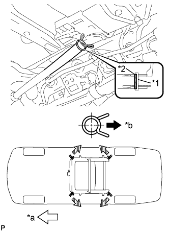
Text in Illustration *1 Clip *2 Marking *a Front Side *b Outside -
Expand the clip to insert the sliding roof drain hose.
Tech Tips
The hose should be inserted to the base of the drain pipe.
-
Release the clip to connect the sliding roof drain hose.
Note
The clip must face toward the outside of the vehicle and also be above the lower surface of the sliding roof housing when installing the drain hoses.
Tech Tips
-
Make sure that the clip is on the marking or between the marking and hose end.
-
Use the same procedure for the other 3 sliding roof drain hoses.
-
-
-
-
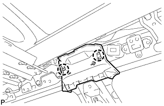
INSTALL REAR NO. 2 SIDE RAIL SPACER LH
-
Engage the 2 claws to install the rear No. 2 side rail spacer LH.
-
-
INSTALL REAR NO. 2 SIDE RAIL SPACER RH
Tech Tips
Use the same procedure as for the LH side.
-
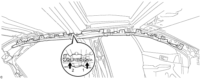
INSTALL CURTAIN SHIELD AIRBAG ASSEMBLY LH
-
Check that the power switch is off.
-
Check that the cable is disconnected from the negative (-) auxiliary battery terminal.
CAUTION:
Wait at least 90 seconds after disconnecting the cable from the negative (-) auxiliary battery terminal to disable the SRS system.
-
Temporarily install the curtain shield airbag assembly with the 2 hooks.
Note
-
When installing the curtain shield airbag assembly, have assistants hold it to prevent it from bending.
-
Do not twist the curtain shield airbag assembly when installing it.
-
-
Install 2 new bolts in the order shown in the illustration.
- Torque:
- 11 N*m { 110 kgf*cm, 8 ft.*lbf }
-
Install the curtain shield airbag assembly to the body panel with 5 claws, 6 new clips and 2 new spacers in the order shown in the illustration.
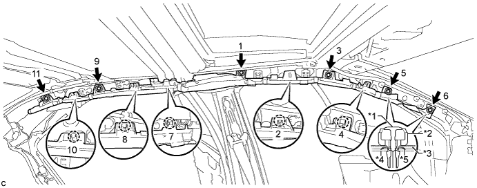
Text in Illustration *1 Pin *2 Clip *3 Curtain Shield Airbag Assembly *4 Body Panel *5 Spacer - - -
Push in a new pin to each clip.
Note
Make sure that the pins of the clips are pushed in firmly.
-
Connect the curtain shield airbag connector.
Text in Illustration *1 Airbag Connector *2 Airbag Connector Lock Note
When connecting any airbag connector, take care not to damage the airbag wire harness.
-
Push in the lock to install the curtain shield airbag connector.
-
-
INSTALL CURTAIN SHIELD AIRBAG ASSEMBLY RH
Tech Tips
Use the same procedure as for the LH side.
-
INSTALL SLIDING ROOF WEATHERSTRIP
-
Install the sliding roof weatherstrip as follows:
-
Position the joint of the weatherstrip at the rear center.
-
Align the alignment mark (yellow) on the weatherstrip with the middle marks at the corners of the sliding roof panel sub-assembly and install the weatherstrip.
-
Install the lip of the weatherstrip firmly.
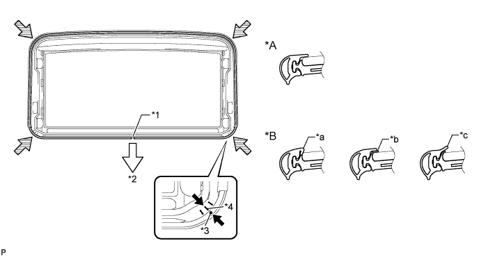
Text in Illustration *1 Joint *2 Rear *3 Alignment Mark (Yellow) *4 Middle Mark *A Normal *B Abnormal *a Pinched *b Exposed *c Gap (raised, wavy, etc.) - -
-
-
-
INSTALL SLIDING ROOF GLASS SUB-ASSEMBLY
-
Using a T25 "TORX" socket wrench, temporarily install the sliding roof glass sub-assembly with the 4 screws.
-
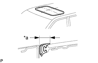
Perform a level check.
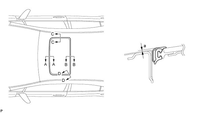
-
Check the difference in level for "a" between the roof panel and the upper surface of the weatherstrip when the sliding roof glass is fully closed.
Standard Area Measurement A - A 0 + 1.0 mm (0 + 0.0394 in.)
0 - 2.0 mm (0 - 0.0787 in.)
B - B 0 + 2.0 mm (0 + 0.0787 in.)
0 - 1.0 mm (0 - 0.0394 in.)
C - C 0 + 1.5 mm (0 + 0.0591 in.)
0 - 1.5 mm (0 - 0.0591 in.)
D - D 0 + 1.5 mm (0 + 0.0591 in.)
0 - 1.0 mm (0 - 0.0394 in.)
Tech Tips
"+" represents the condition that the glass is above the panel level. "-" represents the condition that the glass is below the panel level.
-
-
Perform a gap check.
-
Check the gap between the roof panel and roof glass.
Text in Illustration *a Even Note
The gap must be even all around.
-
-
After adjusting the sliding roof glass, using a T25 "TORX" socket wrench, install the sliding roof glass sub-assembly with the 4 screws.
- Torque:
- 4.0 N*m { 41 kgf*cm, 35 in.*lbf }
-
-
CHECK FOR WATER LEAK
-
After adjusting the sliding roof glass sub-assembly, check for water leakage into the vehicle interior.
-
If there are any leaks, readjust the sliding roof glass sub-assembly.
-
-
INSTALL SLIDING ROOF SIDE GARNISH LH
-
Engage the 2 claws and install the sliding roof side garnish LH.
-
-
INSTALL SLIDING ROOF SIDE GARNISH RH
Tech Tips
Use the same procedure as for the LH side.
-
INSTALL ROOF HEADLINING ASSEMBLY
-
RESET SLIDING ROOF DRIVE GEAR SUB-ASSEMBLY
-
CHECK SLIDING ROOF SYSTEM
-
INSPECT FOR WATER LEAK
-
After adjusting the sliding roof glass sub-assembly, inspect for water leaks.
-
If there are any leaks, readjust the sliding roof glass sub-assembly.
-