POWER WINDOW CONTROL SYSTEM Front Passenger Side Power Window does not Operate with Front Passenger Side Power Window Switch
DESCRIPTION
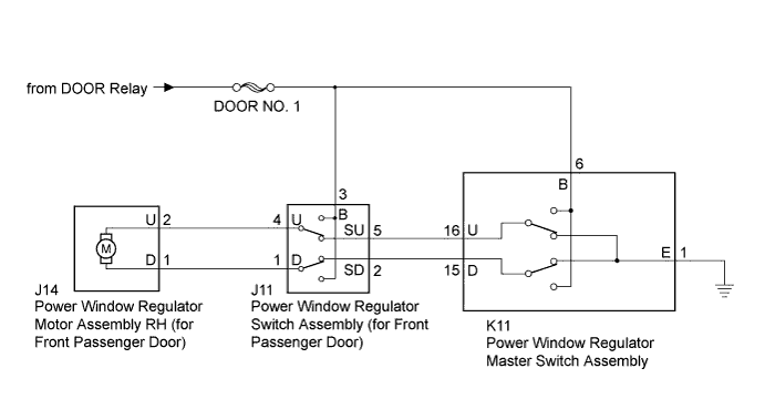
When the power switch is on (IG), the power window regulator motor assembly RH (for front passenger door) is operated by the power window regulator switch assembly (for front passenger door).
WIRING DIAGRAM
INSPECTION PROCEDURE
Note
Inspect the fuses for circuits related to this system before performing the following inspection procedure.
PROCEDURE
-
CHECK HARNESS AND CONNECTOR (POWER WINDOW REGULATOR SWITCH ASSEMBLY (FOR FRONT PASSENGER DOOR) - AUXILIARY BATTERY)
-
Disconnect the J11 power window regulator switch assembly (for front passenger door) connector.
-
Measure the voltage according to the value(s) in the table below.
Standard Voltage Tester Connection Condition Specified Condition J11-3 (B) - Body ground Power switch on (IG) 11 to 14 V
NG 
REPAIR OR REPLACE HARNESS OR CONNECTOR
OK 
-
-
INSPECT POWER WINDOW REGULATOR SWITCH ASSEMBLY (FOR FRONT PASSENGER DOOR)
-
Remove the power window regulator switch assembly (for front passenger door) Click here.
-
Measure the resistance when the switch is operated according to the value(s) in the table below.
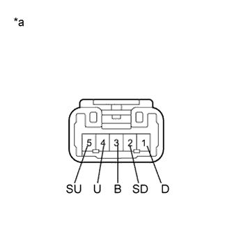
Standard Resistance Tester Connection Condition Specified Condition 1 (D) - 2 (SD) UP Below 1 Ω 3 (B) - 4 (U) Below 1 Ω 1 (D) - 2 (SD) off Below 1 Ω 4 (U) - 5 (SU) Below 1 Ω 4 (U) - 5 (SU) DOWN Below 1 Ω 1 (D) - 3 (B) Below 1 Ω Text in Illustration *a Component without harness connected
(Power Window Regulator Switch Assembly (for Front Passenger Door))
NG
REPLACE POWER WINDOW REGULATOR SWITCH ASSEMBLY (FOR FRONT PASSENGER DOOR) Click here
OK
-
-
CHECK HARNESS AND CONNECTOR (POWER WINDOW REGULATOR SWITCH (FOR FRONT PASSENGER DOOR) - POWER WINDOW REGULATOR MOTOR RH)
-
Disconnect the J14 power window regulator motor assembly RH (for front passenger door) connector.
-
Measure the resistance according to the value(s) in the table below.
Standard Resistance Tester Connection Condition Specified Condition J11-4 (U) - J14-2 (U) Always Below 1 Ω J11-1 (D) - J14-1 (D) Always Below 1 Ω J11-4 (U) - Body ground Always 10 kΩ or higher J11-1 (D) - Body ground Always 10 kΩ or higher
NG
REPAIR OR REPLACE HARNESS OR CONNECTOR
OK
-
-
INSPECT POWER WINDOW REGULATOR MASTER SWITCH ASSEMBLY
-
Remove the power window regulator master switch assembly Click here.
-
Measure the resistance when the switch is operated according to the value(s) in the table below.
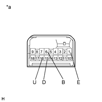
Standard Resistance Tester Connection Condition Specified Condition 6 (B) - 16 (U) UP Below 1 Ω 1 (E) - 15 (D) Below 1 Ω 1 (E) - 16 (U) off Below 1 Ω 1 (E) - 15 (D) Below 1 Ω 6 (B) - 15 (D) DOWN Below 1 Ω 1 (E) - 16 (U) Below 1 Ω Text in Illustration *a Component without harness connected
(Power Window Regulator Master Switch Assembly)
NG
REPLACE POWER WINDOW REGULATOR MASTER SWITCH ASSEMBLY Click here
OK
-
-
CHECK HARNESS AND CONNECTOR (POWER WINDOW REGULATOR MASTER SWITCH - POWER WINDOW REGULATOR SWITCH (FOR FRONT PASSENGER DOOR))
-
Measure the resistance according to the value(s) in the table below.
Standard Resistance Tester Connection Condition Specified Condition K11-16 (U) - J11-5 (SU) Always Below 1 Ω K11-15 (D) - J11-2 (SD) Always Below 1 Ω K11-16 (U) - Body ground Always 10 kΩ or higher K11-15 (D) - Body ground Always 10 kΩ or higher
NG
REPAIR OR REPLACE HARNESS OR CONNECTOR
OK 
REPLACE POWER WINDOW REGULATOR MOTOR ASSEMBLY RH (FOR FRONT PASSENGER DOOR) Click here
-