PTC HEATER ASSEMBLY INSTALLATION

-
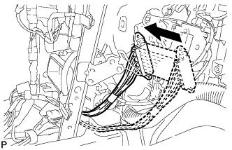
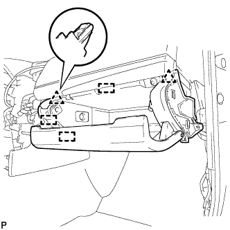
INSTALL QUICK HEATER ASSEMBLY
-
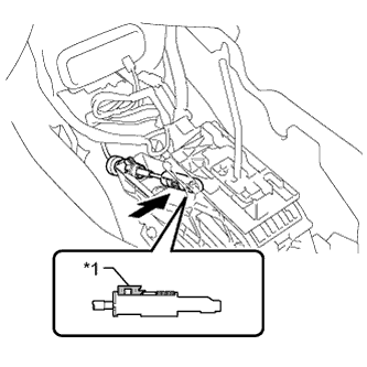
Insert the quick heater assembly as shown in the illustration.
-
Install the 2 screws.
-
Engage the 4 clamps.
-
Install the quick heater assembly with the bolt.
- Torque:
- 20 N*m { 199 kgf*cm, 14 ft.*lbf }
-
Connect the quick heater connector.
-
-
INSTALL SHIFT LEVER SUPPORT
-
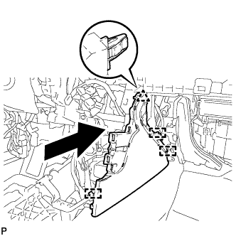
Install the shift lever support with the 4 bolts in the sequence shown in the illustration.
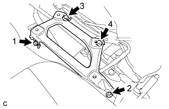
- Torque:
- 12 N*m { 122 kgf*cm, 9 ft.*lbf }
-
-
INSTALL LOWER SHIFT LEVER ASSEMBLY
Note
Check that the park/neutral position switch and the shift lever are in neutral.
-
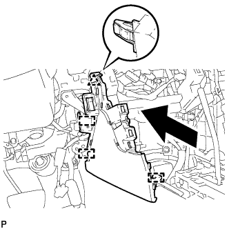
Install the lower shift lever assembly with the 4 bolts in the sequence shown in the illustration.
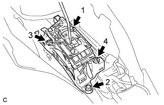
- Torque:
- 12 N*m { 122 kgf*cm, 9 ft.*lbf }
-
Connect the 3 clamps and connector.
-
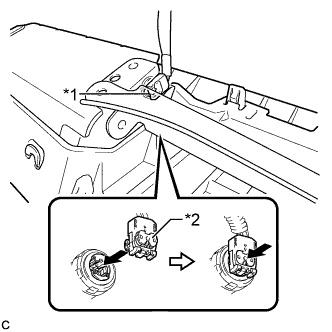
Slide the slider of the transmission control cable in the direction indicated by the arrow and pull the lock piece outward.
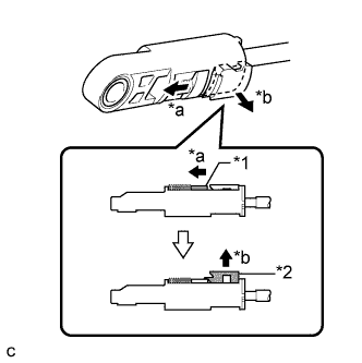
Text in Illustration *1 Slider *2 Lock Piece *a Slide *b Pull -
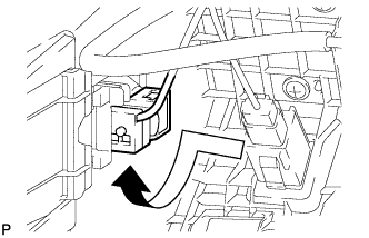
Install the end of the transmission control cable to the shift lever assembly.
Text in Illustration *1 Lock Piece Note
-
Check that the lock piece is pulled up.
-
Install the cable end all the way to the base of the pin.
-
-
Push the lock piece into the adjuster case.
Note
-
Check that the park/neutral position switch and the shift lever are in neutral.
-
Securely push in the lock piece until the slider lock is engaged.
-
-
-
INSTALL NO. 1 CONSOLE BOX DUCT (w/ Rear Register Duct)
-
Install the No. 1 console box duct with the clip.
-
-
INSTALL NO. 1 CONSOLE BOX MOUNTING BRACKET
-
Install the No. 1 console mounting bracket with the screw.
-
-
INSTALL FLOOR CARPET BRACKET LH
-
Engage the 2 guides.
-
Install the floor carpet bracket LH with the 2 clips.
-
-
INSTALL FLOOR CARPET BRACKET RH
-
Engage the 2 guides.
-
Install the floor carpet bracket RH with the 2 clips.
-
-
INSTALL CONSOLE BOX INSERT
-
Engage the clip and 3 guides.
-
Install the console box insert with the 2 screws <D> or <E>.
-
-
INSTALL FRONT NO. 2 CONSOLE BOX INSERT
-
Engage the 2 claws to connect the room temperature sensor.
-
Engage the clip and 3 guides.
-
Install the front No. 2 console box insert with the 2 screws <D> or <E>.
-
-
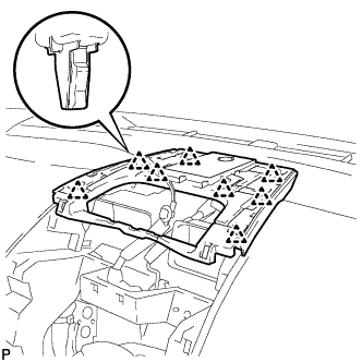
INSTALL LOWER INSTRUMENT PANEL FINISH PANEL ASSEMBLY
-
Connect the connector.
-
Engage the 4 clips and guide to install the lower instrument panel finish panel assembly.
-
-
INSTALL LOWER INSTRUMENT PANEL SUB-ASSEMBLY
-
Connect each connector.
-
Engage the glove compartment light as shown in the illustration.
-
Engage the 3 guides and 2 clips.
-
Install the lower instrument panel sub-assembly with the 5 screws <D> or <E>.
-
-
INSTALL LOWER NO. 2 INSTRUMENT PANEL AIRBAG ASSEMBLY
-
Check that the power switch is off.
-
Check that the cable is disconnected from the negative (-) auxiliary battery terminal.
CAUTION:
Wait at least 90 seconds after disconnecting the cable from the negative (-) auxiliary battery terminal to disable the SRS system.
-
Connect the airbag connector to the lower No. 2 instrument panel airbag assembly.
Note
When connecting any airbag connector, take care not to damage the airbag wire harness.
Text in Illustration *1 Airbag Connector *2 Airbag Connector Lock -
Push in the lock to install the airbag connector.
-
Temporarily install the lower No. 2 instrument panel airbag assembly with the 3 claws.
-
Install the 3 bolts.
- Torque:
- 10 N*m { 102 kgf*cm, 7 ft.*lbf }
Note
Confirm that the lower No. 2 instrument panel airbag assembly is installed securely without any excessive gaps and is not protruding outward.
-
-
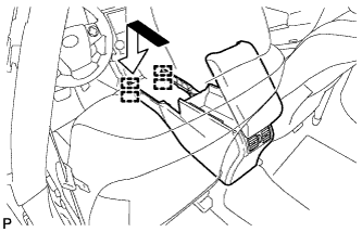
INSTALL NO. 2 INSTRUMENT PANEL UNDER COVER SUB-ASSEMBLY
-
Connect the connector.
-
Engage the 2 guides and 4 claws to install the No. 2 instrument panel under cover sub-assembly.
-
-
INSTALL INSTRUMENT SIDE PANEL RH
-
Engage the 3 guides.
-
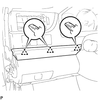
Engage the 4 claws to install the instrument side panel RH as shown in the illustration.
-
-
INSTALL FRONT DOOR OPENING TRIM WEATHERSTRIP RH
-
Align the alignment mark (White) on the weatherstrip with the protruding portion on the body indicated by the arrow in the illustration, and install the front door opening trim weatherstrip RH.
Text in Illustration *1 Alignment Mark (White) Note
After installation, check that the corners fit correctly.
-
-
INSTALL COWL SIDE TRIM SUB-ASSEMBLY RH
Tech Tips
Use the same procedure as for the LH side.
-
INSTALL FRONT DOOR SCUFF PLATE RH
Tech Tips
Use the same procedure as for the LH side Click here.
-
INSTALL NO. 1 SPEAKER OPENING COVER ASSEMBLY
-
Connect the connector.
-
Engage the 8 clips to install the No. 1 speaker opening cover assembly.
-
-
INSTALL RADIO RECEIVER ASSEMBLY WITH AIR CONDITIONING CONTROL ASSEMBLY (for Radio Receiver Type)
-
Connect each connector.
-
Engage the 8 clips to the vehicle body to temporarily install the radio receiver assembly with air conditioning control assembly.
-
Install the radio receiver assembly with air conditioning control assembly with the 4 bolts.
-
-
INSTALL RADIO RECEIVER ASSEMBLY WITH AIR CONDITIONING CONTROL ASSEMBLY (for Radio and Display Type)
-
Connect each connector.
-
Engage the 8 clips to the vehicle body to temporarily install the radio receiver assembly with air conditioning control assembly.
-
Install the radio receiver assembly with air conditioning control assembly with the 4 bolts.
-
-
INSTALL NAVIGATION RECEIVER ASSEMBLY WITH AIR CONDITIONING CONTROL ASSEMBLY (for Navigation Receiver Type)
-
Connect each connector.
-
Engage the 8 clips to the vehicle body to temporarily install the navigation receiver assembly with air conditioning control assembly.
-
Install the navigation receiver assembly with air conditioning control assembly with the 4 bolts.
-
-
INSTALL UPPER CONSOLE PANEL SUB-ASSEMBLY
-
Connect each connector.
-
Engage the 4 clips and guide.
-
Install the upper console panel sub-assembly with the 2 screws <D> or <E>.
-
-
INSTALL BOX BOTTOM MAT
-
Install the box bottom mat.
-
-
INSTALL NO. 2 INSTRUMENT PANEL REGISTER ASSEMBLY
-
Engage the 6 clips to install the No. 2 instrument panel register assembly.
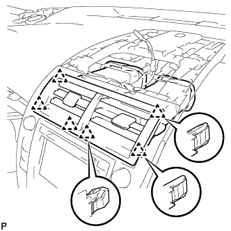
Note
When installing the No. 2 instrument panel register assembly, check that the wire harness is not caught between the No. 2 instrument panel register assembly and duct.
-
-
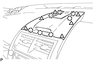
INSTALL CENTER INSTRUMENT CLUSTER FINISH PANEL ASSEMBLY
-
Connect the connector.
-
Engage the clamp.
-
Engage the 6 clips and 7 claws to install the center instrument cluster finish panel assembly.
-
-
INSTALL REAR CONSOLE BOX ASSEMBLY
-
Engage the 4 guides as shown in the illustration.
-
Install the rear console box assembly with the 2 bolts and 2 screws.
-
-
INSTALL CONSOLE BOX CARPET
-
Install the console box carpet.
-
-
INSTALL NO. 4 CONSOLE BOX DUCT
-
Engage the claw to install the No. 4 console box duct.
-
-
INSTALL UPPER CONSOLE BOX SUB-ASSEMBLY
-
Connect the connector and engage the clamp.
-
Engage the 2 guides and 4 clips as shown in the illustration.

-
Install the upper console box sub-assembly with the 2 screws.
-
-
INSTALL REAR CONSOLE UPPER PANEL SUB-ASSEMBLY
-
Connect each connector.
-
Engage the 4 clips and install the rear console upper panel sub-assembly.
-
Move the shift lever to P.
-
-
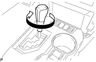
INSTALL SHIFT LEVER KNOB SUB-ASSEMBLY
-
Turn the shift lever knob sub-assembly clockwise to install the shift lever knob sub-assembly.
-
-
INSTALL FRONT PANEL GARNISH RH
-
Engage the 3 claws, 2 clips and 8 guides to install the front panel garnish RH.
-
-
INSTALL LOWER NO. 1 INSTRUMENT PANEL FINISH PANEL ASSEMBLY
-
Engage the 4 claws, 9 clips and 3 guides.
-
Install the lower No. 1 instrument panel finish panel assembly with the bolt <C> and screw <D> or <E>.
-
-
CONNECT HOOD LOCK CONTROL LEVER SUB-ASSEMBLY
-
Engage the claw and 2 guides to connect the hood lock control lever sub-assembly.
-
-
INSTALL NO. 1 INSTRUMENT CLUSTER FINISH PANEL GARNISH
-
Engage the 3 clips to install the No. 1 instrument cluster finish panel garnish.
-
-
INSTALL FRONT PANEL GARNISH LH
-
Engage the 3 claws, 2 clips and 8 guides to install the front panel garnish LH.
-
-
INSTALL INSTRUMENT SIDE PANEL LH
-
Engage the 3 guides.
-
Engage the 4 claws to install the instrument side panel LH as shown in the illustration.
-
-
INSTALL FRONT DOOR OPENING TRIM WEATHERSTRIP LH
-
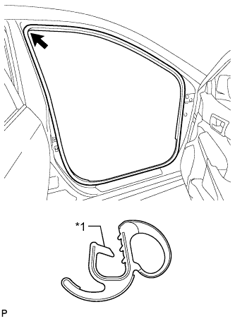
Align the alignment mark (Yellow) on the weatherstrip with the protruding portion on the body indicated by the arrow in the illustration, and install the front door opening trim weatherstrip LH.
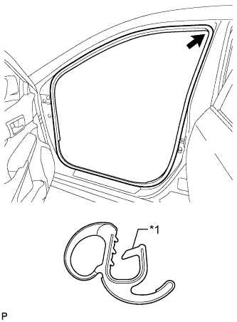
Text in Illustration *1 Alignment Mark (Yellow) Note
After installation, check that the corners fit correctly.
-
-
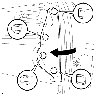
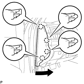
INSTALL COWL SIDE TRIM SUB-ASSEMBLY LH
-
Insert the 2 clips in the direction indicated by the arrows shown in the illustration to engage them.
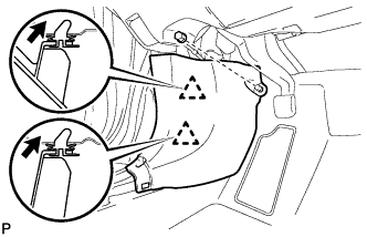
-
Install the cowl side trim sub-assembly LH with the clip.
-
-
INSTALL FRONT DOOR SCUFF PLATE LH
-
Engage the 10 claws to install the front door scuff plate LH.
-
-
INSTALL FRONT SEAT ASSEMBLY LH (for Manual Seat)
-
INSTALL FRONT SEAT ASSEMBLY LH (for Power Seat)
-
INSTALL FRONT SEAT ASSEMBLY RH (for Manual Seat)
Tech Tips
Use the same procedure as for the LH side.
-
INSTALL FRONT SEAT ASSEMBLY RH (for Power Seat)
Tech Tips
Use the same procedure as for the LH side.
-
INSPECT SHIFT LEVER POSITION
-
While moving the shift lever from the N position to each position, check that the lever moves smoothly and that the shift position indicator comes on properly according to the shift lever position.
-
Put the vehicle into the READY-on state and check the following:
-
When the shift lever is moved to the D position, the vehicle moves forward.
-
When the shift lever is moved to the R position, the vehicle moves in reverse.
Note
The vehicle should not move when the shift position indicator is off.
-
-