PTC HEATER ASSEMBLY REMOVAL

-
REMOVE FRONT SEAT ASSEMBLY LH (for Manual Seat)
-
REMOVE FRONT SEAT ASSEMBLY LH (for Power Seat)
-
REMOVE FRONT SEAT ASSEMBLY RH (for Manual Seat)
Tech Tips
Use the same procedure as for the LH side.
-
REMOVE FRONT SEAT ASSEMBLY RH (for Power Seat)
Tech Tips
Use the same procedure as for the LH side.
-
REMOVE FRONT DOOR SCUFF PLATE LH
-
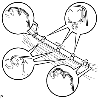
Disengage the 10 claws and remove the front door scuff plate LH.
-
-
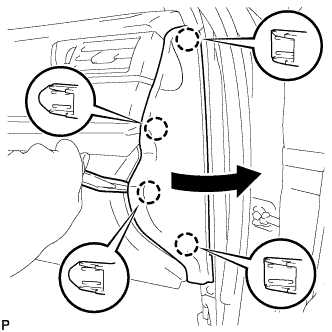
REMOVE COWL SIDE TRIM SUB-ASSEMBLY LH
-
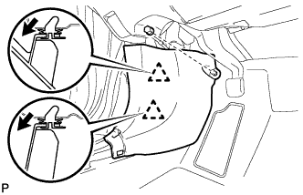
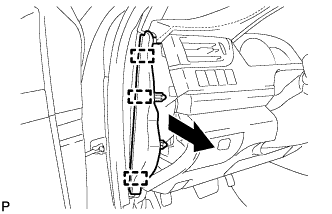
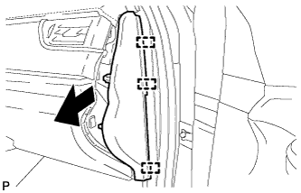
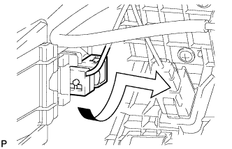
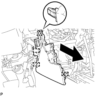
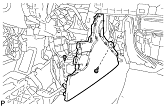
Remove the clip.
-
Pull the cowl side trim sub-assembly LH in the direction indicated by the arrow shown in the illustration to disengage the 2 clips and remove the cowl side trim sub-assembly LH.
-
-
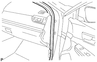
DISCONNECT FRONT DOOR OPENING TRIM WEATHERSTRIP LH
-
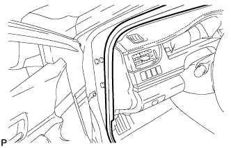
Disconnect the front door opening trim weatherstrip LH.
-
-
REMOVE INSTRUMENT SIDE PANEL LH
-
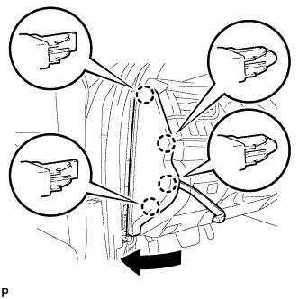
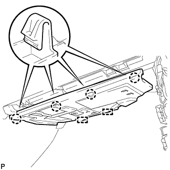
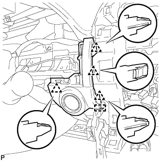
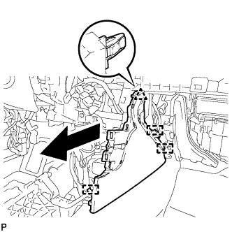
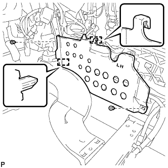
Using a moulding remover, disengage the 4 claws as shown in the illustration.
-
Disengage the 3 guides and remove the instrument side panel LH as shown in the illustration.
-
-
REMOVE NO. 1 INSTRUMENT CLUSTER FINISH PANEL GARNISH
-
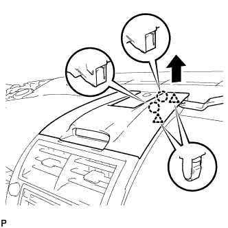
Disengage the 3 clips to remove the No. 1 instrument cluster finish panel garnish as shown in the illustration.
-
-
REMOVE FRONT PANEL GARNISH LH
-
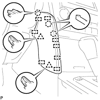
Disengage the 3 claws, 2 clips and 8 guides to remove the front panel garnish LH.
-
-
DISCONNECT HOOD LOCK CONTROL LEVER SUB-ASSEMBLY
-
Disengage the claw and 2 guides to disconnect the hood lock control lever sub-assembly.
-
-
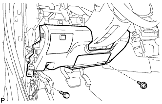
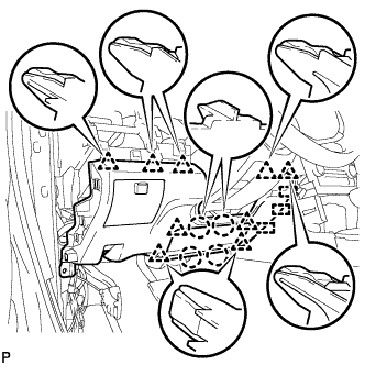
REMOVE LOWER NO. 1 INSTRUMENT PANEL FINISH PANEL ASSEMBLY
-
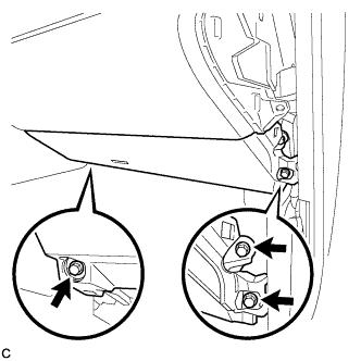
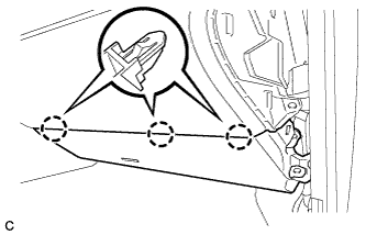
Remove the bolt <C> and screw <D> or <E>.
-
Disengage the 4 claws, 9 clips and 3 guides to remove the lower No. 1 instrument panel finish panel assembly.
-
-
REMOVE FRONT PANEL GARNISH RH
-
Disengage the 3 claws, 2 clips and 8 guides to remove the front panel garnish RH.
-
-
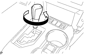
REMOVE SHIFT LEVER KNOB SUB-ASSEMBLY
-
Turn the shift lever knob sub-assembly counterclockwise and remove the shift lever knob sub-assembly.
-
-
REMOVE REAR CONSOLE UPPER PANEL SUB-ASSEMBLY
-
Open the upper console panel sub-assembly door.
-
Move the shift lever to N.
-
Disengage the 4 clips.
-
Disconnect each connector and remove the rear console upper panel sub-assembly.
-
-
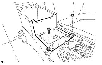
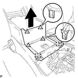
REMOVE UPPER CONSOLE BOX SUB-ASSEMBLY
-
Remove the 2 screws.
-
Disengage the 4 clips and 2 guides remove the upper console box sub-assembly as shown in the illustration.
-
Disengage the clamp.
-
Disconnect the connector to remove the upper console box sub-assembly.
-
-
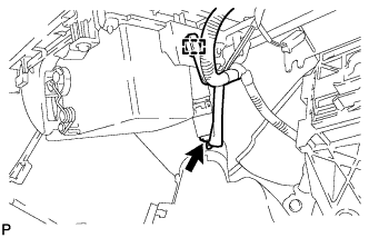
REMOVE NO. 4 CONSOLE BOX DUCT
-
Disengage the claw and remove the No. 4 console box duct.
-
-
REMOVE CONSOLE BOX CARPET
-
Remove the console box carpet.
-
-
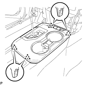
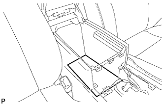
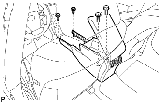
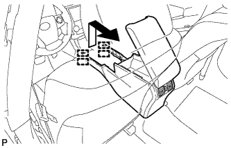
REMOVE REAR CONSOLE BOX ASSEMBLY
-
Remove the 2 bolts and 2 screws.
-
Pull the rear console box assembly in the direction indicated by the arrow to disengage the 4 guides and remove the rear console box assembly.
-
-
REMOVE CENTER INSTRUMENT CLUSTER FINISH PANEL ASSEMBLY
-
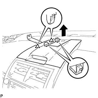
Using a moulding remover, disengage the 2 claws and 2 clips as shown in the illustration.
-
Using a moulding remover, disengage the 2 claws and 2 clips as shown in the illustration.
-
Disengage the 3 claws and 2 clips as shown in the illustration.
-
Disengage the clamp.
-
Disconnect the connector to remove the center instrument cluster finish panel assembly.
-
-
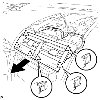
REMOVE NO. 2 INSTRUMENT PANEL REGISTER ASSEMBLY
-
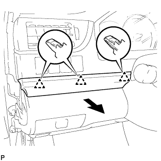
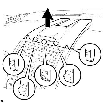
Pull the No. 2 instrument panel register assembly in the direction indicated by the arrow to disengage the 6 clips to remove the No. 2 instrument panel register assembly.
-
-
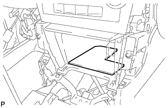
REMOVE BOX BOTTOM MAT
-
Remove the box bottom mat.
-
-
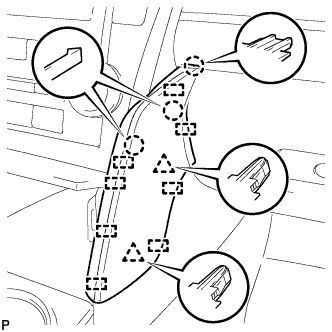
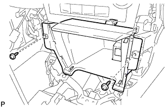
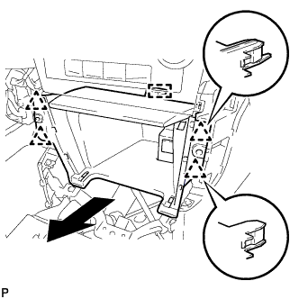
REMOVE UPPER CONSOLE PANEL SUB-ASSEMBLY
-
Remove the 2 screws <D> or <E>.
-
Disengage the 4 clips and guide as shown in the illustration.
-
Disconnect each connector to remove the upper console panel sub-assembly.
-
-
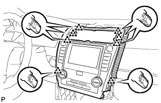
REMOVE RADIO RECEIVER ASSEMBLY WITH AIR CONDITIONING CONTROL ASSEMBLY (for Radio Receiver Type)
-
Apply protective tape to the area shown in the illustration.
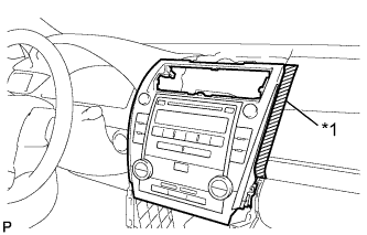
Text in Illustration *1 Protective Tape -
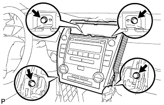
Remove the 4 bolts.
-
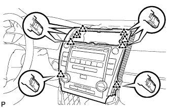
Pull the radio receiver assembly with air conditioning control assembly toward the rear of the vehicle and disengage the 8 clips.
-
Disconnect each connector and remove the radio receiver assembly with air conditioning control assembly.
-
-
REMOVE RADIO RECEIVER ASSEMBLY WITH AIR CONDITIONING CONTROL ASSEMBLY (for Radio and Display Type)
-
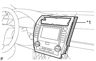
Apply protective tape to the areas shown in the illustration.
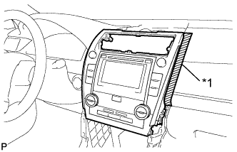
Text in Illustration *1 Protective Tape -
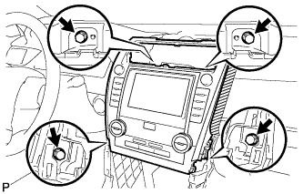
Remove the 4 bolts.
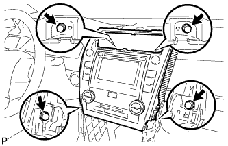
-
Pull the radio receiver assembly with air conditioning control assembly toward the rear of the vehicle and disengage the 8 clips.
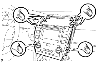
-
Disconnect each connector and remove the radio receiver assembly with air conditioning control assembly.
Tech Tips
w/ Navigation System:Do not disconnect the extension module connector.
-
-
REMOVE NAVIGATION RECEIVER ASSEMBLY WITH AIR CONDITIONING CONTROL ASSEMBLY (for Navigation Receiver Type)
-
Apply protective tape to the areas shown in the illustration.
Text in Illustration *1 Protective Tape -
Remove the 4 bolts.
-
Pull the navigation receiver assembly with air conditioning control assembly toward the rear of the vehicle and disengage the 8 clips.
-
Disconnect each connector and remove the navigation receiver assembly with air conditioning control assembly.
-
-
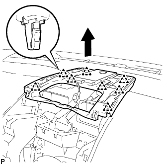
REMOVE NO. 1 SPEAKER OPENING COVER ASSEMBLY
-
Disengage the 8 clips as shown in the illustration.
-
Disconnect the connector to remove the No. 1 speaker opening cover assembly.
-
-
REMOVE FRONT DOOR SCUFF PLATE RH
Tech Tips
Use the same procedure as for the LH side Click here.
-
REMOVE COWL SIDE TRIM SUB-ASSEMBLY RH
Tech Tips
Use the same procedure as for the LH side Click here.
-
DISCONNECT FRONT DOOR OPENING TRIM WEATHERSTRIP RH
-
Disconnect the front door opening trim weatherstrip RH.
-
-
REMOVE INSTRUMENT SIDE PANEL RH
-
Using a moulding remover, disengage the 4 claws as shown in the illustration.
-
Disengage the 3 guides to remove the instrument side panel RH as shown in the illustration.
-
-
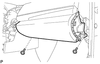
REMOVE NO. 2 INSTRUMENT PANEL UNDER COVER SUB-ASSEMBLY
-
Disengage the 4 claws and 2 guides.
-
Disconnect the connector and remove the No. 2 instrument panel under cover sub-assembly.
-
-
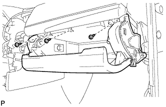
REMOVE LOWER NO. 2 INSTRUMENT PANEL AIRBAG ASSEMBLY
CAUTION:
When storing the lower No. 2 instrument panel airbag assembly, keep the airbag deployment side facing upward.
-
Check that the power switch is off.
-
Check that the cable is disconnected from the negative (-) auxiliary battery terminal.
CAUTION:
Wait at least 90 seconds after disconnecting the cable from the negative (-) auxiliary battery terminal to disable the SRS system.
-
Remove the 3 bolts.
-
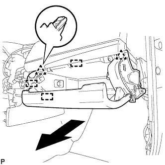
Disengage the 3 claws to remove the lower No. 2 instrument panel airbag assembly.
Note
When removing the lower No. 2 instrument panel airbag assembly, do not pull the airbag wire harness.
-
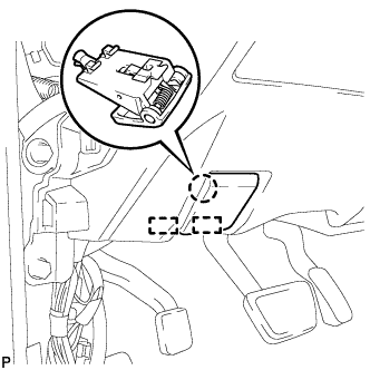
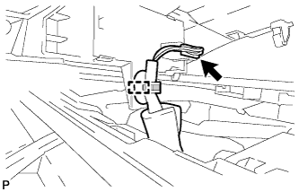
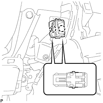
Using a screwdriver with the tip wrapped with protective tape, release the airbag connector lock.
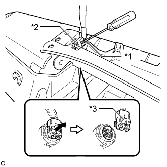
Text in Illustration *1 Protective Tape *2 Airbag Connector *3 Airbag Connector Lock -
Disconnect the airbag connector to remove the lower No. 2 instrument panel airbag assembly.
Note
When disconnecting any airbag connector, take care not to damage the airbag wire harness.
-
-
REMOVE LOWER INSTRUMENT PANEL SUB-ASSEMBLY
-
Remove the 2 screws <D> or <E>.
-
Open the lower instrument panel door.
-
Remove the 3 screws <D> or <E>.
-
Disengage the 2 clips and 3 guides.
-
Disengage the glove compartment light as shown in the illustration.
-
Disconnect each connector and remove the lower instrument panel sub-assembly.
-
-
REMOVE LOWER INSTRUMENT PANEL FINISH PANEL ASSEMBLY
-
Disengage the 4 clips and guide.
-
Disconnect the connector and remove the lower instrument panel finish panel assembly.
-
-
REMOVE FRONT NO. 2 CONSOLE BOX INSERT
-
Disengage the 2 claws to disconnect the room temperature sensor from the front No. 2 console box insert.
-
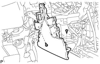
Remove the 2 screws <D> or <E>.
-
Disengage the clip and 3 guides to remove the front No. 2 console box insert as shown in the illustration.
-
-
REMOVE CONSOLE BOX INSERT
-
Remove the 2 screws <D> or <E>.
-
Disengage the clip and 3 guides to remove the console box insert as shown in the illustration.
-
-
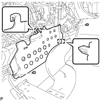
REMOVE FLOOR CARPET BRACKET LH
-
Remove the 2 clips.
-
Disengage the 2 guides to remove the floor carpet bracket LH.
-
-
REMOVE FLOOR CARPET BRACKET RH
-
Remove the 2 clips.
-
Disengage the 2 guides to remove the floor carpet bracket RH.
-
-
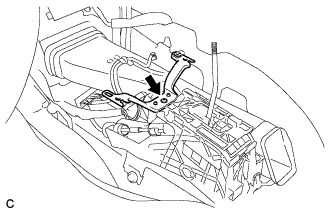
REMOVE NO. 1 CONSOLE BOX MOUNTING BRACKET
-
Remove the screw and No. 1 console box mounting bracket from the lower shift lever assembly.
-
-
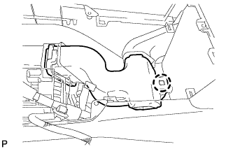
REMOVE NO. 1 CONSOLE BOX DUCT (w/ Rear Register Duct)
-
Remove the clip and the No. 1 console box duct.
-
-
REMOVE LOWER SHIFT LEVER ASSEMBLY
-
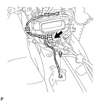
Disconnect the end of transmission control cable assembly from the lower shift lever assembly.
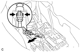
-
Disengage the 2 claws and disconnect the transmission control cable assembly from the lower shift lever assembly.
-
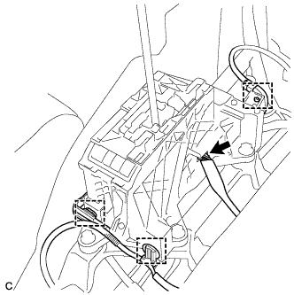
Disconnect the 3 clamps and connector.
-
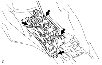
Remove the 4 bolts and lower shift lever assembly.
-
-
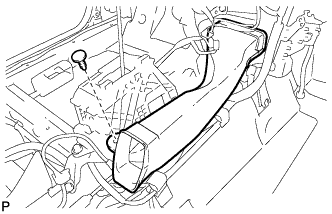
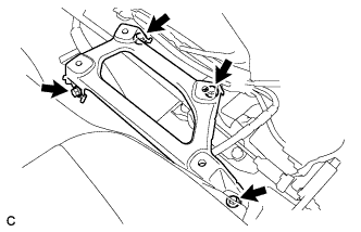
REMOVE SHIFT LEVER SUPPORT
-
Remove the 4 bolts and shift lever support.
-
-
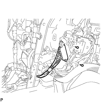
REMOVE QUICK HEATER ASSEMBLY
-
Disconnect the quick heater connector.
-
Remove the bolt.
-
Disengage the 4 clamps.
-
Remove the 2 screws.
-
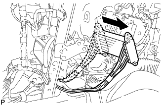
Remove the quick heater assembly as shown in the illustration.
-