AIR CONDITIONING UNIT REMOVAL

Note
Make sure to select FACE mode before disconnecting the cable from the negative (-) auxiliary battery terminal.
-
RECOVER REFRIGERANT FROM AIR CONDITIONING SYSTEM
-
Turn the power switch on (READY).
-
Turn the A/C switch on.
-
Operate the cooler compressor under the conditions shown below:
Item Condition Engine Speed Idling Operating Time 3 minutes or more A/C Switch Status ON Blower Switch Status HI Set Temperature MAX COOL This cause most of the compressor oil from the various components of the A/C system to collect in the A/C compressor.
Tech Tips
It is not necessary to operate the cooler compressor if the A/C does not operate because of compressor lock etc.
-
Turn the power switch off.
-
Recover the refrigerant from the air conditioning system using a refrigerant recovery unit.
Tech Tips
Use the refrigerant recover unit in accordance with the manufacturer's instruction manual.
-
-
REMOVE WINDSHIELD WIPER MOTOR AND LINK ASSEMBLY
-
REMOVE FRONT OUTER COWL TOP PANEL SUB-ASSEMBLY
-
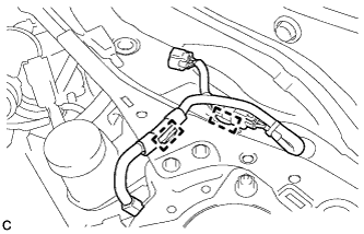
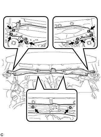
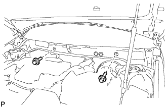
Disengage the 2 clamps and separate the wire harness from the front outer cowl top panel sub-assembly.
-
Remove the 10 bolts and front outer cowl top panel sub-assembly.
-
-
DISCONNECT HEATER OUTLET WATER HOSE
-
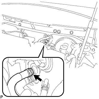
Using pliers, grip the claws of the clip and slide the clip to disconnect the heater outlet water hose.
Note
-
Do not apply excessive force to the heater outlet water hose.
-
Prepare a drain pan or cloth in case the coolant leaks.
-
-
-
DISCONNECT HEATER INLET WATER HOSE
-
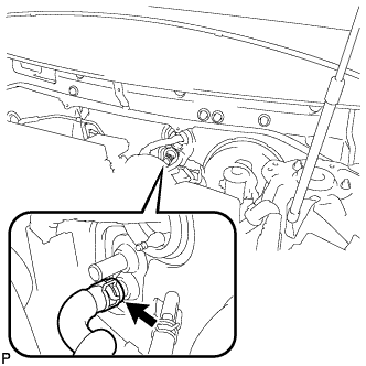
Using pliers, grip the claws of the clip and slide the clip to disconnect the heater inlet water hose.
Note
-
Do not apply excessive force to the heater inlet water hose.
-
Prepare a drain pan or cloth in case the coolant leaks.
-
-
-
DISCONNECT SUCTION HOSE SUB-ASSEMBLY
-
Remove the bolt, and slide the hook connector.
-
Disconnect the suction hose sub-assembly.
-
Remove the O-ring from the suction hose sub-assembly.
Note
Seal the openings of the disconnected parts using vinyl tape to prevent entry of moisture and foreign matter.
-
-
DISCONNECT AIR CONDITIONER TUBE AND ACCESSORY ASSEMBLY
-
Disconnect the air conditioner tube and accessory assembly.
-
Remove the O-ring from the air conditioner tube and accessory assembly.
Note
Seal the openings of the disconnected parts using vinyl tape to prevent entry of moisture and foreign matter.
-
-
REMOVE FRONT SEAT ASSEMBLY LH (for Manual Seat)
-
REMOVE FRONT SEAT ASSEMBLY LH (for Power Seat)
-
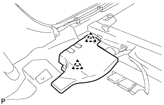
REMOVE AUDIO AMPLIFIER COVER (for 10 Speakers)
-
Using a clip remover, remove the 2 clips and audio amplifier cover.
-
-
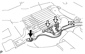
REMOVE STEREO COMPONENT AMPLIFIER ASSEMBLY WITH BRACKET (for 10 Speakers)
-
Remove the bolt and disconnect the ground wire.
-
Disconnect each connector.
-
Disengage the clamp.
-
Remove the bolt.
-
Disengage the 2 guides and remove the stereo component amplifier assembly with bracket.
-
-
REMOVE FRONT SEAT ASSEMBLY RH (for Manual Seat)
Tech Tips
Use the same procedure for the RH side and LH side.
-
REMOVE FRONT SEAT ASSEMBLY RH (for Power Seat)
Tech Tips
Use the same procedure for the RH side and LH side.
-
REMOVE AUDIO AMPLIFIER COVER (w/ Manual (SOS) Switch)
-
Using a clip remover, remove the 2 clips and audio amplifier cover.
-
-
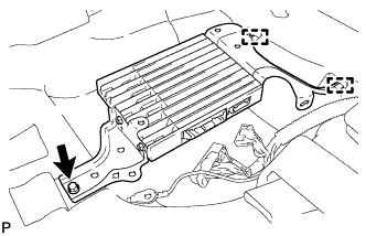
REMOVE DCM (TELEMATICS TRANSCEIVER) WITH BACK-UP BATTERY (w/ Manual (SOS) Switch)
-
Disconnect each connector.
-
Disengage the 3 clamps.
-
Remove the bolt.
-
Disengage the 2 guides and remove the DCM (telematics transceiver) with back-up battery.
-
-
REMOVE INSTRUMENT PANEL SAFETY PAD ASSEMBLY
-
REMOVE STEERING POST ASSEMBLY
-
REMOVE POWER MANAGEMENT CONTROL ECU
-
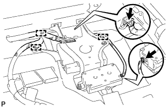
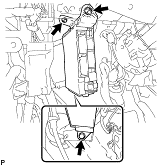
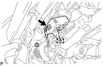
REMOVE INSTRUMENT PANEL JUNCTION BLOCK ASSEMBLY
-
Disconnect the 5 connectors.
-
Remove the bolt and 2 nuts, and disconnect the instrument panel junction block assembly.
-
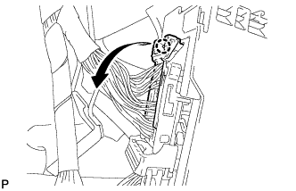
Disengage the claw and disconnect the connector as shown in the illustration.
-
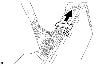
Disengage the claw and release the connector lock as shown in the illustration.
-
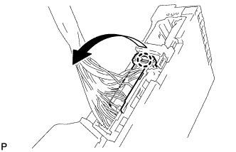
Disengage the claw and disconnect the connector as shown in the illustration to remove the instrument panel junction block assembly.
-
-
REMOVE VEHICLE APPROACHING SPEAKER CONTROLLER
-
Disconnect the connector.
-
Remove the nut.
-
Disengage the guide to remove the vehicle approaching speaker controller.
-
-
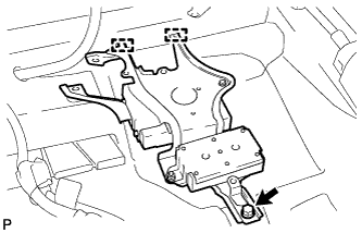
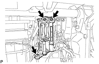
REMOVE ECU INTEGRATION BOX RH
-
Disconnect each connector.
-
Remove the bolt, 2 nuts and ECU integration box RH.
-
-
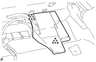
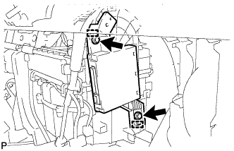
REMOVE AIR CONDITIONING AMPLIFIER ASSEMBLY
-
Disconnect each connector.
-
Remove the 2 screws.
-
Disengage the 2 guides and remove the air conditioning amplifier assembly.
-
-
REMOVE FLOOR CARPET HOOK
-
Disengage the 6 guides.
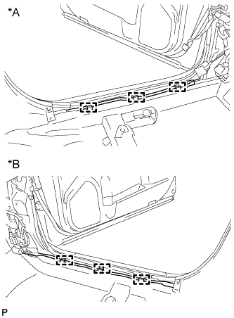
Text in Illustration *A for LH Side *B for RH Side -
Disengage the 6 claws and remove the 6 floor carpet hooks.
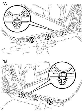
Text in Illustration *A for LH Side *B for RH Side
-
-
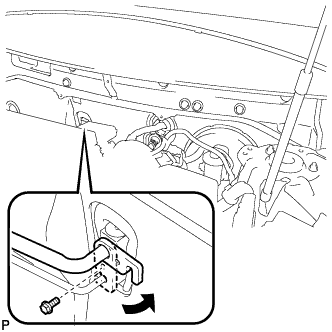
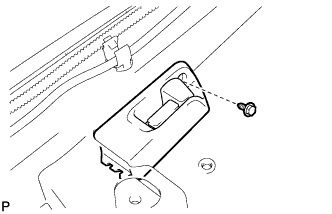
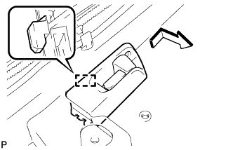
DISCONNECT FUEL LID LOCK OPEN LEVER SUB-ASSEMBLY
-
Remove the screw.
-
Disengage the guide to disconnect the fuel lid lock open lever sub-assembly as shown in the illustration.
-
-
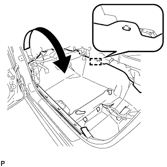
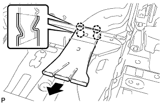
REMOVE REAR NO. 4 AIR DUCT
-
Disengage the guide.
-
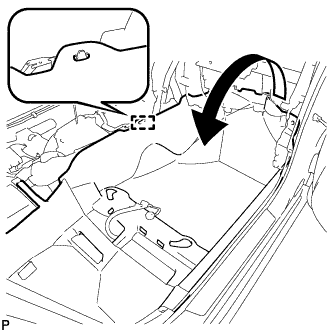
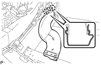
Turn back the floor carpet as shown in the illustration.
-
Disengage the 4 claws to remove the rear No. 4 air duct.
-
-
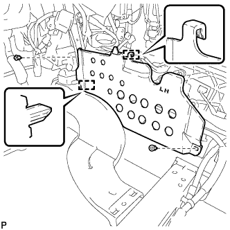
REMOVE FLOOR CARPET BRACKET LH
-
Remove the 2 clips.
-
Disengage the 2 guides to remove the floor carpet bracket LH.
-
-
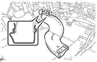
REMOVE REAR NO. 3 AIR DUCT
-
Disengage the 2 claws to remove the rear No. 3 air duct.
-
-
REMOVE REAR NO. 2 AIR DUCT
-
Disengage the guide.
-
Turn back the floor carpet as shown in the illustration.
-
Disengage the 4 claws to remove the rear No. 2 air duct.
-
-
REMOVE FLOOR CARPET BRACKET RH
-
Remove the 2 clips.
-
Disengage the 2 guides to remove the floor carpet bracket RH.
-
-
REMOVE REAR NO. 1 AIR DUCT
-
Disengage the 2 claws to remove the rear No. 1 air duct.
-
-
REMOVE NO. 1 CONSOLE BOX MOUNTING BRACKET
-
Remove the screw and No. 1 console box mounting bracket from the lower shift lever assembly.
-
-
REMOVE NO. 1 CONSOLE BOX DUCT (w/ Rear Register Duct)
-
Remove the clip and the No. 1 console box duct.
-
-
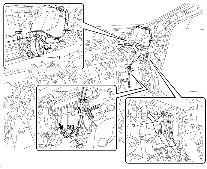
REMOVE INSTRUMENT PANEL TO COWL BRACE SUB-ASSEMBLY
-
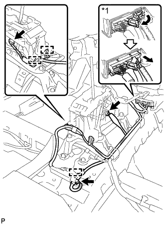
Disconnect each connector.
Text in Illustration *1 Earth Wire -
Disengage each clamp.
-
Disconnect the connector.
-
Disengage each clamp.
-
Remove the bolt and 2 nuts.
-
Remove the screw and the instrument panel to cowl brace sub-assembly.
-
-
REMOVE NO. 2 INSTRUMENT PANEL BRACE SUB-ASSEMBLY
-
Disconnect the connector.
Text in Illustration *1 Earth Wire -
Disengage each clamp.
-
Remove the bolt and disconnect the earth wire.
-
Remove the bolt and 2 nuts.
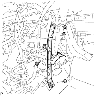
-
Remove the screw and the No. 2 instrument panel brace sub-assembly.
-
-
REMOVE INSTRUMENT PANEL SAFETY PAD CAP
-
Put protective tape around the 5 instrument panel safety pad caps.
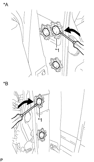
Text in Illustration *A for LH Side *B for RH Side *1 Protective Tape -
Using a screwdriver, remove the 5 instrument panel safety pad caps.
-
-
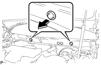
REMOVE FRONT LOWER PANEL PACKING
-
Remove the 2 front lower panel packings as shown in the illustration.
-
-
REMOVE INSTRUMENT PANEL REINFORCEMENT ASSEMBLY WITH AIR CONDITIONING UNIT
Note
-
Be sure to support the air conditioning unit assembly when removing it because failure to do so may cause the bracket of the air conditioning unit assembly to break.
-
When disassembling the air conditioning unit, eliminate static electricity by touching the vehicle body to prevent the components from being damaged.
-
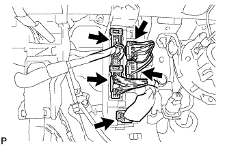
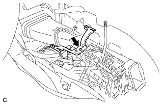
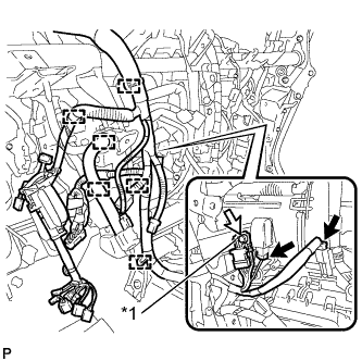
Disengage 3 claws to open the 3 clamps.
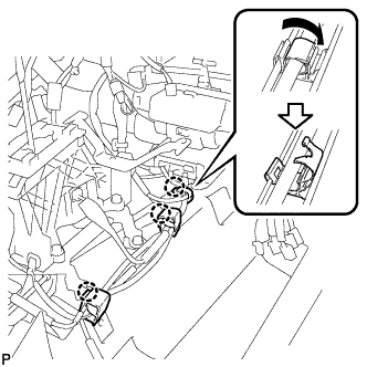
-
Disconnect the center airbag sensor connectors from the center airbag sensor assembly as shown in the illustration.
Text in Illustration *1 Center Airbag Sensor Connector Note
When disconnecting any airbag connector, take care not to damage the airbag wire harness.
-
Disconnect the 3 connectors.
-
Disengage the 3 clamps.
-
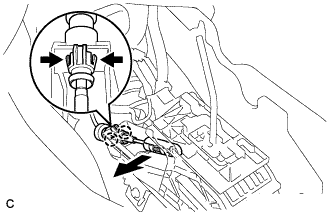
Move the shift lever to N.
-
Disconnect the end of the transmission control cable assembly from the lower shift lever assembly.
-
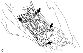
Remove the 4 bolts and lower shift lever assembly.
-
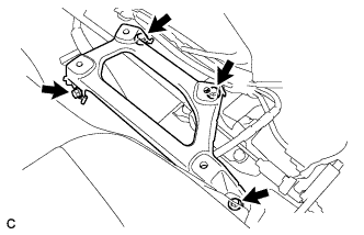
Remove the 4 bolts and shift lever support.
-
Remove the bolt.
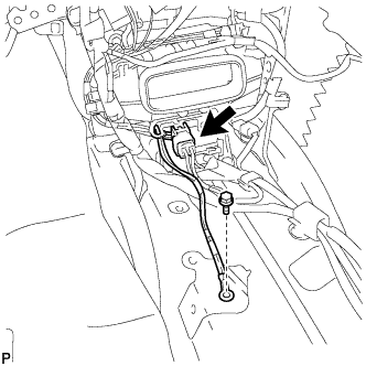
-
Disconnect the connector.
-
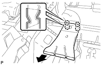
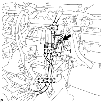
Using a screwdriver, disengage the 2 claws to unlock the retainer as shown in the illustration.
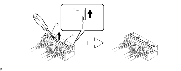
Text in Illustration *1 Retainer *2 Protective Tape -
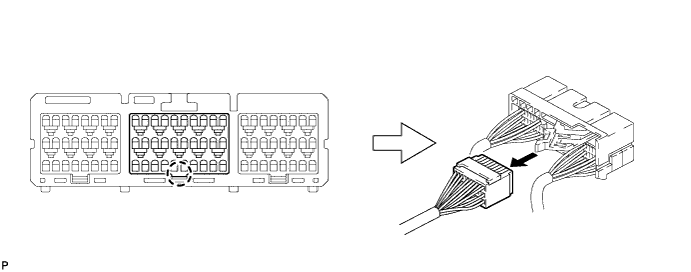
Disengage the claw and disconnect the airbag connector as shown in the illustration.
-
Disengage each clamp.
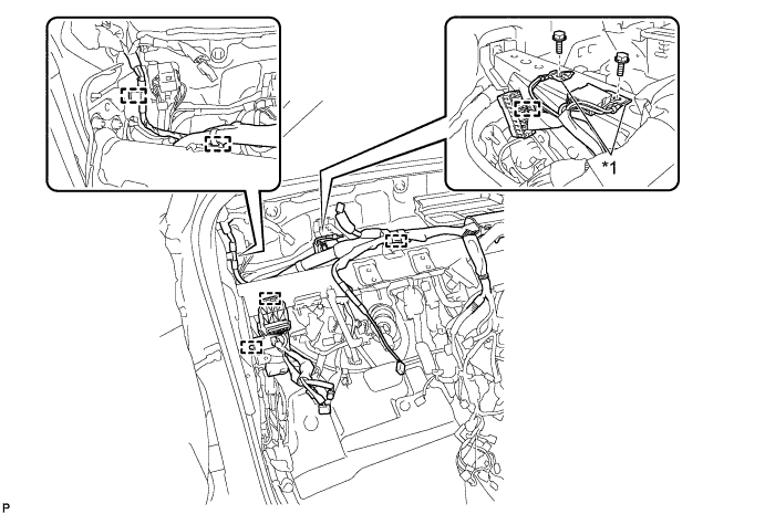
Text in Illustration *1 Earth Wire - - -
Remove the 2 bolts and disconnect the 2 earth wires.
-
Disconnect the connector.

-
Disengage each clamp.
-
Remove the 2 nuts.
-
Remove the bolt and disconnect the earth wire.
Text in Illustration *1 Earth Wire *2 Connector Holder -
Disengage each clamp.
-
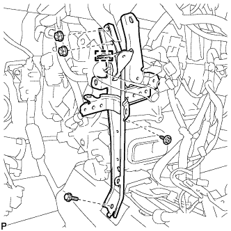
Remove the 2 bolts.
-
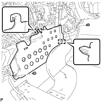
Remove the 5 bolts and the nut as shown in the illustration.
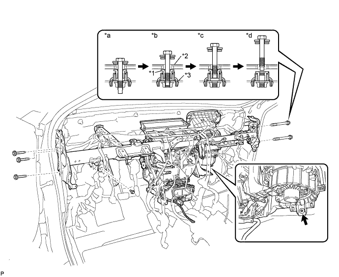
Text in Illustration *1 Movable Collar *2 Body *3 Instrument Panel Reinforcement - - *a Step 1 *b Step 2 *c Step 3 *d Step 4 -
Remove the instrument panel reinforcement assembly with air conditioning unit with the nut.
-
Disconnect the cooler drain hose.
-
Remove the bolt.
-
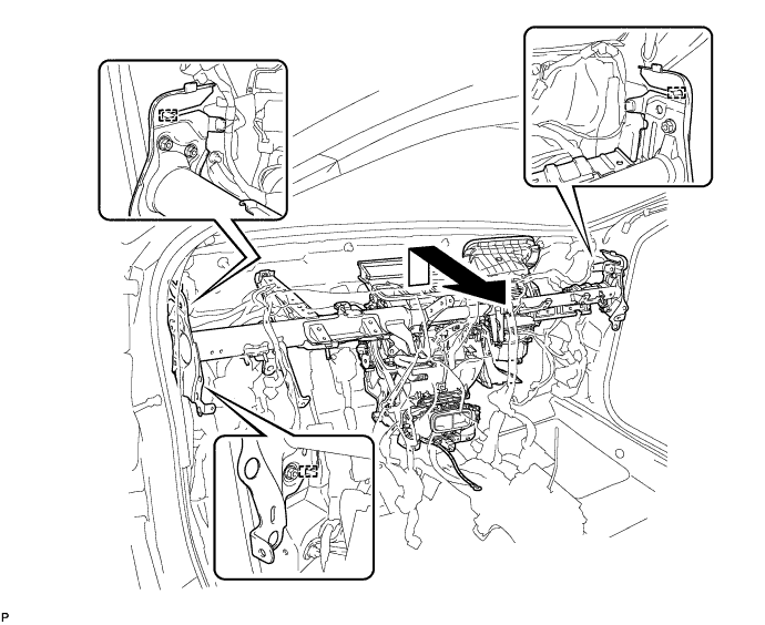
Disengage the 3 guides and remove the instrument panel reinforcement with air conditioning unit as shown in the illustration.
-
-
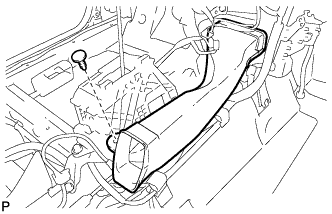
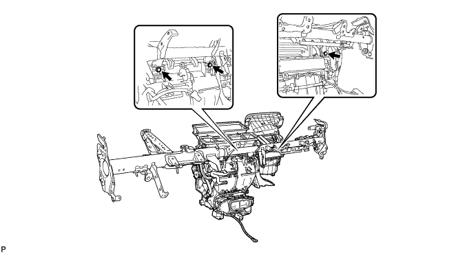
REMOVE AIR CONDITIONING UNIT ASSEMBLY
-
Remove the 3 bolts and the air conditioning unit assembly from the instrument panel reinforcement assembly.
-