COMPRESSOR REMOVAL

-
RECOVER REFRIGERANT FROM AIR CONDITIONING SYSTEM
-
Turn the power switch on (READY).
-
Turn the A/C switch on.
-
Operate the cooler compressor under the conditions shown below:
Item Condition Engine Speed Idling Operating Time 3 minutes or more A/C Switch Status ON Blower Switch Status HI Set Temperature MAX COOL This cause most of the compressor oil from the various components of the A/C system to collect in the A/C compressor.
Tech Tips
It is not necessary to operate the cooler compressor if the A/C does not operate because of compressor lock etc.
-
Turn the power switch off.
-
Recover the refrigerant from the air conditioning system using a refrigerant recovery unit.
Tech Tips
Use the refrigerant recover unit in accordance with the manufacturer's instruction manual.
-
-
REMOVE SERVICE PLUG GRIP
-
REMOVE RADIATOR ASSEMBLY
-
CHECK TERMINAL VOLTAGE
-
Remove the connector cover assembly Click here.
-
Check the terminal voltage Click here.
-
Install the connector cover assembly Click here.
-
-
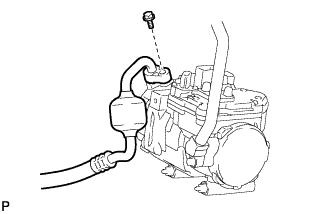
DISCONNECT NO. 1 COOLER REFRIGERANT DISCHARGE HOSE
-
Remove the bolt and disconnect the No. 1 cooler refrigerant discharge hose from the compressor with motor assembly.
-
Remove the O-ring from the No. 1 cooler refrigerant discharge hose.
Note
Seal the openings of the disconnected parts using vinyl tape to prevent entry of moisture and foreign matter.
-
-
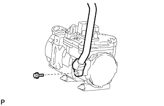
DISCONNECT SUCTION HOSE SUB-ASSEMBLY
-
Remove the bolt and disconnect the suction hose sub-assembly from the compressor with motor assembly.
-
Remove the O-ring from the suction hose sub-assembly .
Note
Seal the openings of the disconnected parts using vinyl tape to prevent entry of moisture and foreign matter.
-
-
REMOVE COMPRESSOR WITH MOTOR ASSEMBLY
-
Disconnect connector B.
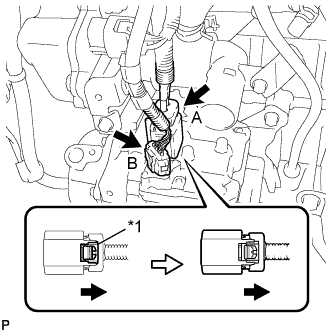
Text in Illustration *1 Green-colored Lock -
Release the green-colored lock and disconnect connector A as shown in the illustration.
CAUTION:
Wear insulated gloves when performing the following steps.
Note
Insulate the connector by sealing it with tape.
-
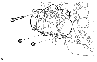
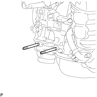
Remove the bolt and 2 nuts and compressor with motor assembly.
-
Using an E8 "TORX" socket, remove the 2 stud bolts.
-