BODY STRUCTURE
-
CONSTRUCTION
-
Body Shell
-
The position of the body's structural parts is optimized, optimized connection methods are used and reinforcing materials are provided, creating a lightweight body structure with high rigidity and ensuring driving stability.
-
-
Engine Compartment Brace
-
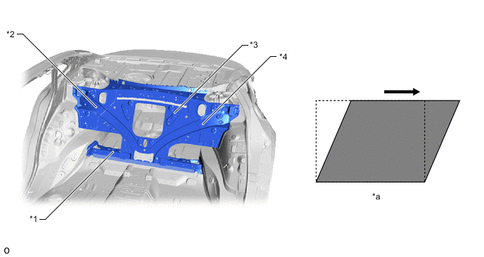
6 braces are optimally positioned inside the engine compartment to achieve high rigidity in the front body. As a result, superior driving stability is achieved.
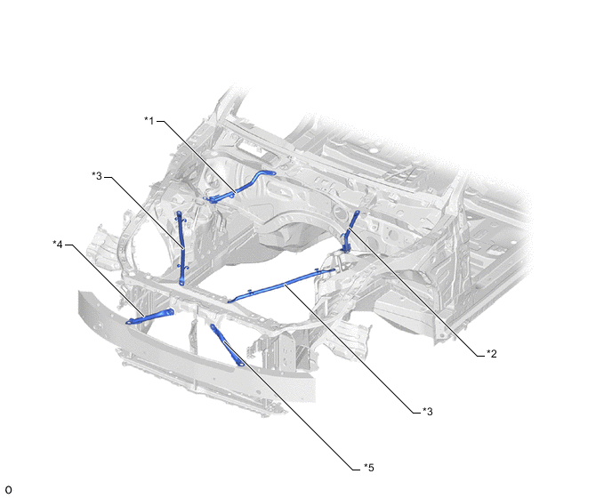
*1 Fender Apron Brace Sub-assembly RH *2 Fender Apron Brace Sub-assembly LH *3 Radiator Support To Cross Member Brace Sub-assembly *4 Lower Arm Bracket Brace Sub-assembly RH *5 Lower Arm Bracket Brace Sub-assembly LH - -
-
-
Suspension Tower
-
An aluminum die-cast* suspension tower (front spring support and rear suspension spring support) is used to optimize the thickness and rib shape to achieve superior body rigidity and weight reduction.
Tech Tips
*: A method in which molten aluminum alloy, zinc alloy, etc. are forced into a mold cavity under high pressure to forge parts.
Figure 1. Front Suspension Tower
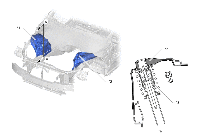
*1 Front Spring Support RH *2 Front Spring Support LH *3 Front Suspension - - *a A - A Cross Section *b Rib Shape Increases Rigidity of Suspension Installation Area Figure 2. Rear Suspension Tower
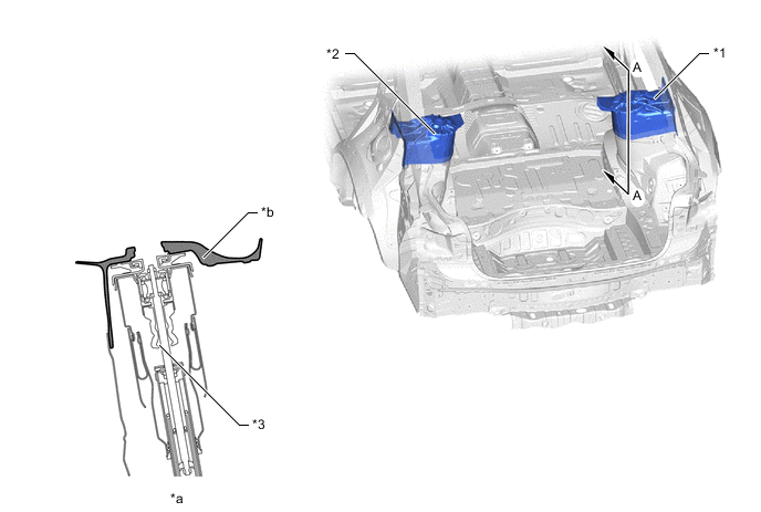
*1 Rear Suspension Spring Support RH *2 Rear Suspension Spring Support LH *3 Rear Suspension - - *a A - A Cross Section *b Rib Shape Increases Rigidity of Suspension Installation Area
-
-
Cowl Top Side Stiffening Structure
-
The cowl is given an underbody structure that connects the closed cross section of the cowl to the front body pillars and creates a ring structure for the cowl and instrument panel reinforcement assembly to achieve high rigidity for the cowl area. As a result, superior driving stability is achieved.
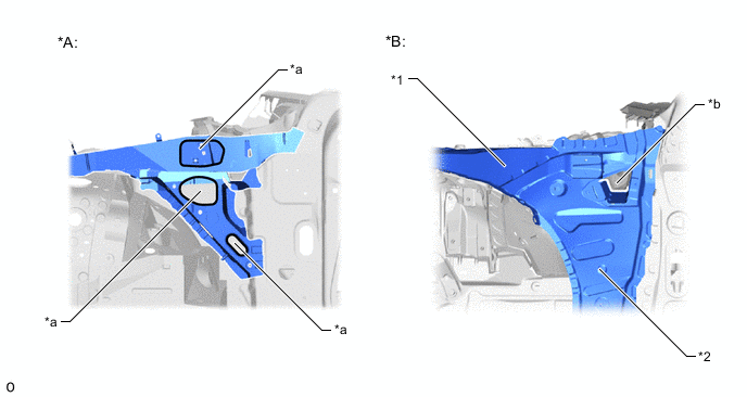
*A Conventional Welding Method *B LS *1 Cowl Top Side Panel LH *2 Front Body Pillar Gusset LWR LH *a Service Hole *b Drainage Hole
-
-
High-rigidity Urethane Sealant
-
A high-rigidity urethane sealant is used to adhere the windshield glass and back window glass to the vehicle to improve body rigidity and ensure excellent driving stability.
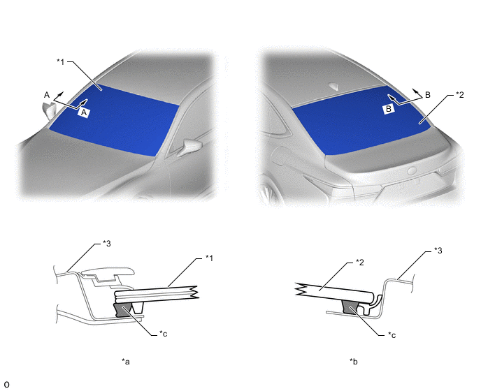
*1 Windshield Glass *2 Back Window Glass *3 Side Panel OUTER RH - - *a A - A Cross Section *b B - B Cross Section *c High-rigidity Urethane Sealant - -
-
-
Cowl and Instrument Panel Reinforcement Ring Structure
-
The cowl is given an underbody structure that connects the closed cross section of the cowl to the front body pillars and creates a ring structure for the cowl and instrument panel reinforcement assembly to achieve high rigidity for the cowl area. As a result, superior driving stability is achieved.
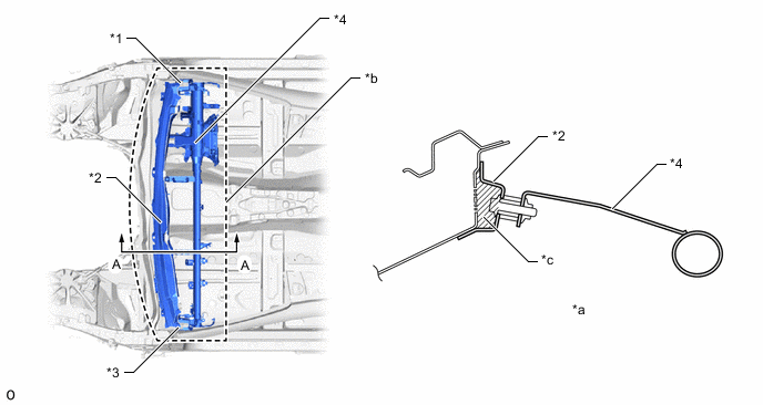
*1 Instrument Panel To Cowl Bracket No. 1 *2 Cowl Top Reinforcement INNER *3 Instrument Panel To Cowl Bracket No. 2 *4 Instrument Panel Reinforcement Assembly *a A - A Cross Section *b Ring Structure *c Closed Cross Section - -
-
-
Rocker
-
A large rocker cross section is provided to increase body rigidity, achieving superior driving stability.
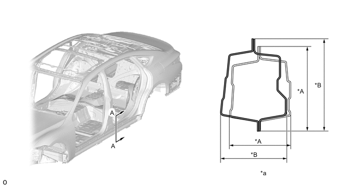
*A Conventional Model *B LS *a A - A Cross Section - -
-
-
Floor Cross Member Continuous Flange Structure
-
A continuous flange is used in the floor cross member frame connection area to increase the rigidity of the frame connection, achieving superior driving stability.
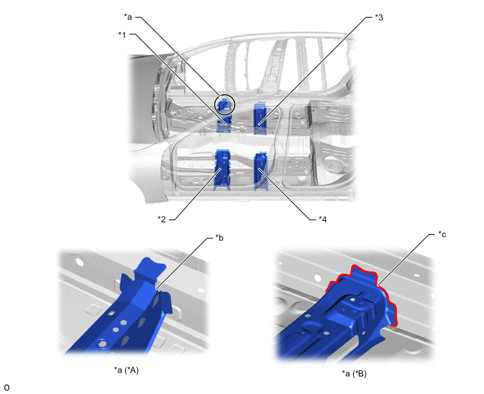
*A Conventional Model *B LS *1 Front Floor Cross Member RH *2 Front Floor Cross Member LH *3 Front Floor Cross Side Member RH *4 Front Floor Cross Side Member LH *a Floor Cross Member Frame Connection Area *b Cutout *c Continuous Flange - -
-
-
Large Floor Brace
-
A large brace (front floor brace sub-assembly center) is provided on the bottom of the floor to increase body rigidity, achieving superior driving stability.
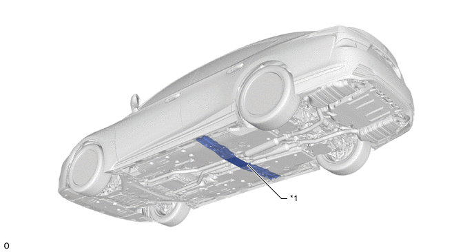
*1 Front Floor Brace Sub-assembly Center - -
-
-
Rear Floor Cross Member
-
A rear floor cross member (rear floor cross member FR), which connects both sides of the rear wheel house, is provided to increase vehicle torsional rigidity, achieving superior driving stability.
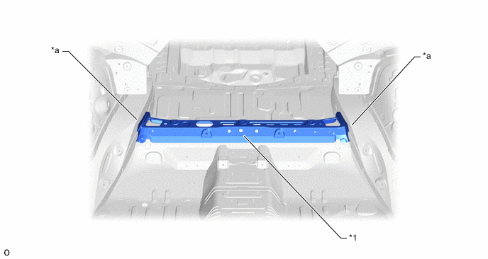
*1 Rear Floor Cross Member FR - - *a Rear Wheel House - -
-
-
Structural Adhesive, Laser Welding, Laser Screw Welding (LSW)
-
Structural adhesive*1, laser welding*2 and Laser Screw Welding (LSW)*3 are used over a large range to increase panel connecting rigidity, ensuring superior driving stability (steering response and feeling).
Tech Tips
*1: Compared to conventional spot welding where panels are only connected at certain points, this adhesive is used together with welds to connect body surfaces, minimizing bending and warping to maximize rigidity.
*2: This method increases panel connectivity in a line between spot welding points by using a connection method that uses a laser as a main heat source to concentrate light on the metal, melting and solidifying it in a localized area.
*3: Compared to conventional spot welding, this method reduces the pitch of welding points, allowing them to be concentrated in areas that need to be connected. Connections can be concentrated around frame openings to strengthen the structure of the vehicle.
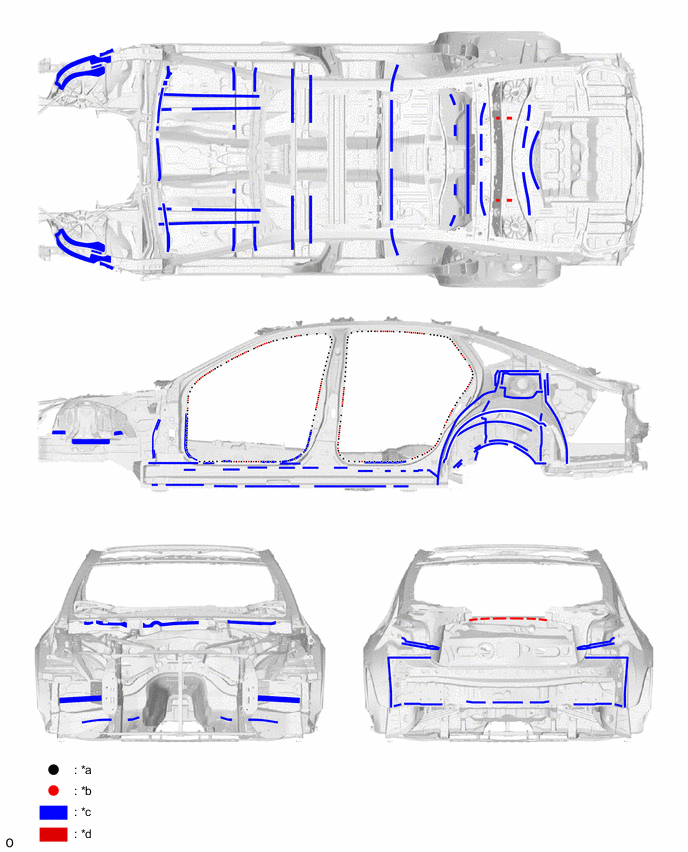
*a Spot Welding *b LSW *c Structural Adhesive *d Laser Welding
-
-
Framework Connecting Rigidity
-
Each panel around the doors is securely connected and given a ring structure to strengthen its connecting rigidity and enhance the torsional rigidity of the body, ensuring superior operational stability (steering response and feeling).
-
The connecting length of the rocker and the lower part of the front body pillar is made longer in the longitudinal direction, ensuring a high level of framework connecting rigidity (A in illustration).
-
The connecting length of the rocker and the upper part of the front body pillar is made longer in the longitudinal direction, ensuring a high level of framework connecting rigidity (B in illustration).
-
The connecting length of the rocker and the lower part of the front body pillar is made longer in the longitudinal direction, ensuring a high level of framework connecting rigidity (C in illustration).
-
The reinforcement (roof side panel inner (*5 in illustration)) that covers even the under surface of the rocker is provided at the rear end of the rocker, ensuring a high level of framework connecting rigidity (D in illustration).
-
A bulkhead (No. 4 side panel gusset UPR (*10 in illustration) is provided at the rear end of the rocker, ensuring a high level of framework connecting rigidity (D in illustration).
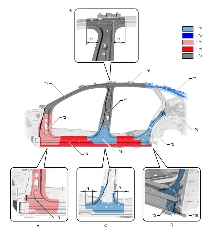
*1 Front Body Pillar Reinforcement UPR OUTER LH *2 Front Body Pillar Reinforcement LWR OUT LH *3 Rocker Panel OUTER LH *4 Center Body Pillar Reinforcement LWR LH *5 Rocker Panel Reinforcement No. 5 LH *6 Roof Side Panel Inner Front LH *7 Roof Side Rail Outer Rear LH *8 Roof Side Rail LH *9 Center Body Pillar Reinforcement UPR LH *10 No. 4 Side Panel Gusset UPR *a High-tensile Strength Steel (Tensile Strength: 440 MPa Class) *b High-tensile Strength Steel (Tensile Strength: 590 MPa Class) *c Ultra High-tensile Strength Steel (Tensile Strength: 980 MPa Class) *d Ultra High-tensile Strength Steel (Tensile Strength: 1180 MPa Class) *e Hot-stamped Steel (Tensile Strength: 1500 MPa Class) *f Widening -
-
-
Room Partition Panel
-
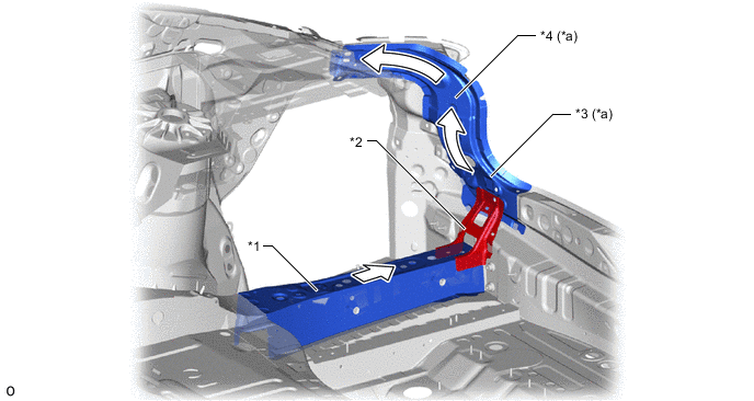
A rear floor cross member FR (*1 in illustration) is provided to connect to the room partition panel (*3 in illustration), suppressing shear strain around the suspension tower and ensuring a high level of framework connecting rigidity.
*1 Rear Floor Cross Member FR *2 Package Tray To Floor Strainer RH *3 Room Partition Panel *4 Package Tray To Floor Strainer LH *a Shearing Strain Image - -
-
-
Rear Body Frame
-
Input impact load from the suspension is dissipated to the roof side rail OUTER RR (*2 in illustration) via the roof side panel INNER FR (*1 in illustration) and to the roof side rail OUTER RR (*2 in illustration) via the roof side panel OUTER (*3 in illustration), suppressing deformation of the back door opening.
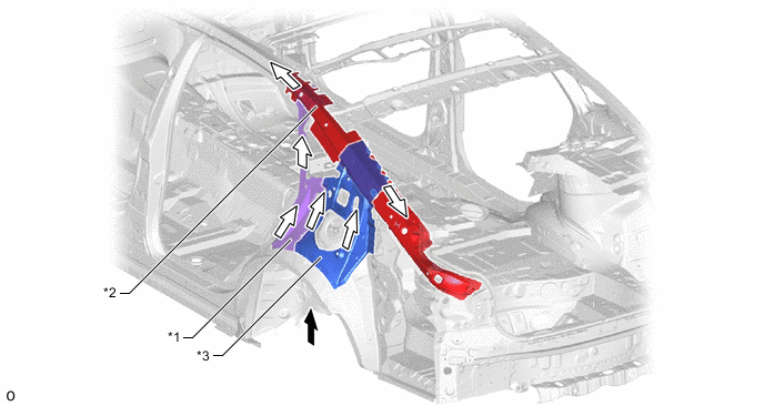
*1 Roof Side Panel INNER FR LH *2 Roof Side Rail OUTER RR LH *3 Roof Side Panel OUTER LH - - 
Input Load from Rear Suspension 
Dissipate -
The rear floor side member rear (*1 in illustration) and quarter panel INNER CTR (*3 in illustration) are connected at the rear floor cross member No. 6 (*2 in illustration) to make connecting the upper body framework and under body framework possible, achieving a structure that supports twisting input using the entire body.
*1 Rear Floor Side Member Rear RH *2 Rear Floor Cross Member No. 6 *3 Quarter Panel INNER CTR RH *4 Quarter Panel Inner RH *a Closed Cross Section Framework - - Transmission of Torsion Moment - -
-
-