BODY STRUCTURE
-
CONSTRUCTION
-
Aero Stabilizing Fin
-
An aero stabilizing fin is provided in the front pillar cover sub-assembly UPR. The air flowing over the aero stabilizing fin generates spiral turbulence behind the fin. This turbulence suppresses air separation from the side of the body, reduces air resistance (the resistance due to the negative pressure that occurs behind physical objects) and laterally presses against the vehicle to ensure superior driving stability.
-
The front door outside handle assembly and rear door outside handle assembly are given shapes with the same feature as the aero stabilizing fin.
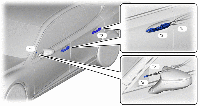
*1 Front Pillar Cover Sub-assembly UPR LH *2 Front Door Outside Handle Assembly LH *3 Rear Door Outside Handle Assembly LH - - *a Aero Stabilizing Fin *b Turbulence
-
-
Aluminum Tape
-
Aluminum tape (molding tape No. 1) is provided on the back of the front bumper cover and rear bumper cover. The body and air become positively charged when driving, making it easier for the air to separate from the body. Aluminum tape that effectively discharges the electrical charge of the vehicle is optimally positioned because air separation generates turbulence and prevents aerodynamic effects. As a result, nearby air separation is suppressed, ensuring superior operational stability.
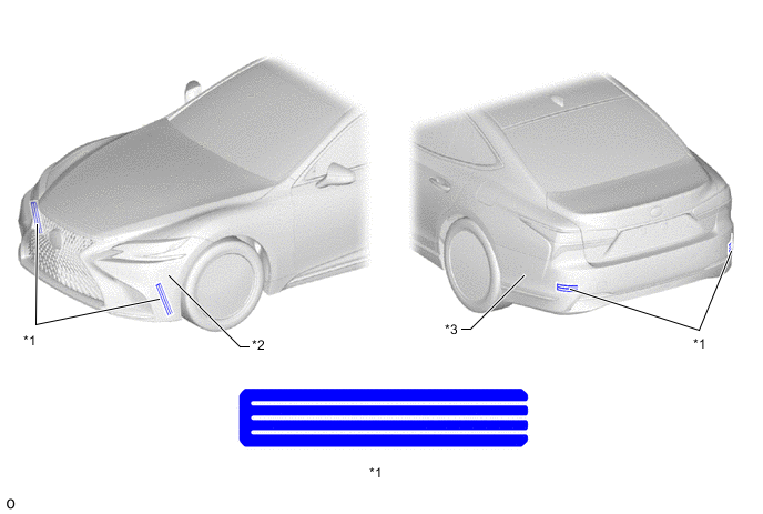
*1 Molding Tape No. 1 *2 Front Bumper Cover *3 Rear Bumper Cover - -
-
-
Under Cover
-
The body rocker panel molding assemblies (*18 and *19 in illustration) are positioned so that they overlap the under cover (*c in illustration). This expands the under cover floor cover range and reduces air resistance of flattened floor components and the under cover, improving fuel efficiency.
-
Aero stabilizing fins are optimally positioned on the underside of the vehicle to adjust the air flowing under the vehicle and effectively generate downforce.
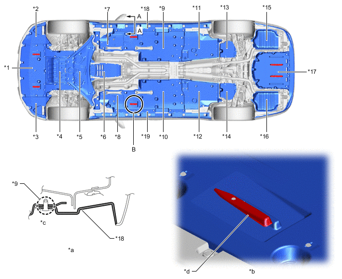
*1 Engine Under Cover Assembly No. 1 *2 Front Fender Liner LH *3 Front Fender Liner RH *4 Strut Bar Bracket Support Sub-assembly *5 Engine Under Cover Assembly No. 2 *6 Transmission Under Cover *7 Front Fender Seal LH *8 Front Fender Seal RH *9 Floor Board Sub-assembly No. 2 *10 Floor Board Sub-assembly *11 Rear Floor Side Member Cover LH *12 Rear Floor Side Member Cover RH *13 Differential Support Protector No. 2 *14 Differential Support Protector No. 1 *15 Muffler Assembly LH *16 Main Muffler Assembly *17 Floor Under Cover No. 1 *18 Body Rocker Panel Molding Assembly LH *19 Body Rocker Panel Molding Assembly RH - - *a A - A Cross Section *b Enlarged Illustration of B *c Overlap Area *d Aero Stabilizing Fin
-
-
Luggage Compartment Panel Shape
-
The rear end shape of the luggage compartment door panel sub-assembly is given an horizontal design to allow the airflow from the roof to securely move to the luggage compartment door panel sub-assembly, achieving air resistance reduction.
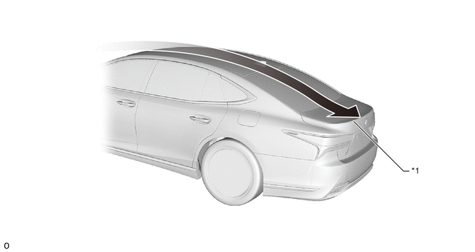
*1 Luggage Compartment Door Panel Sub-assembly - - 
Airflow - -
-
-
Rear End
-
The curving surface shape at the rear side ends and corners of the rear combination light assemblies is made small to clearly separate the airflows, suppressing turbulence generated at the rear of the vehicle. This reduces air resistance.
*1 Rear Combination Lamp Assembly LH - - Airflow - -
-
-
Vertical Fin
-
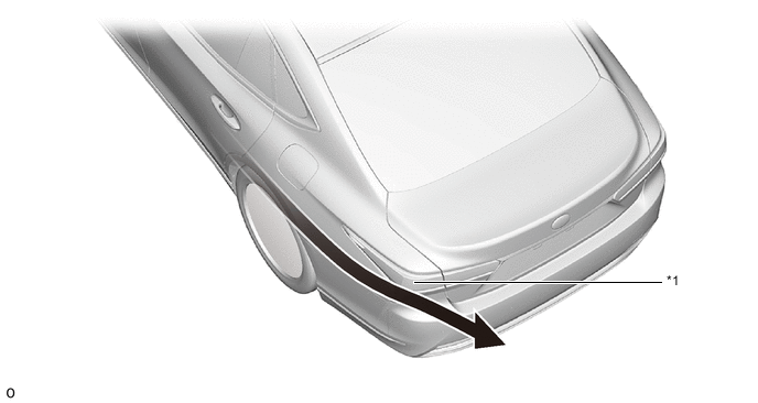
A vertical fin (rear bumper retainer lower) is provided behind the rear tires. The vertical fin suppresses air turbulence flowing behind the rear tires, reducing air resistance and ensuring superior straight-line stability at high speeds and stability against winds from the sides.
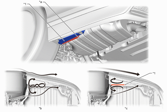
*1 Rear Bumper Retainer Lower LH - - *a Vertical Fin *b Without Fin: Air Turbulence Fluctuates behind Rear Tires *c With Fin: Air Turbulence behind Rear Tires Suppressed and Rectified - - Airflow - -
-
-