BODY STRUCTURE
-
FUNCTION
-
Impact Absorbing Structure for Frontal Collision
-
A multi-load path body structure, which dissipates input load along multiple paths, is used to absorb impact energy during frontal collisions, ensuring superior safety.
-
Impact load from the upper member (*a in illustration) is dissipated to the roof rail (*c in illustration) through the front body pillar (*b in illustration) during frontal collisions.
-
Impact load from the side member (*d in illustration) is dissipated to the rocker (*f in illustration) through the torque box (*b in illustration) during frontal collisions.
Figure 1. Impact Absorbing Structure for Frontal Collision (The illustration shown is an example only.)
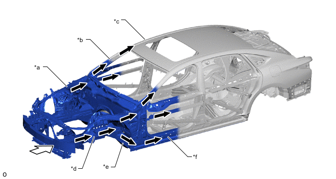
*a Upper Member *b Front Body Pillar *c Roof Rail *d Side Member *e Torque Box *f Rocker 
Front Impact Energy 
Dissipate
-
-
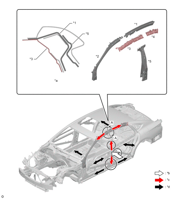
The amount of cabin deformation that occurs during frontal collisions is suppressed using the following structures.
-
A front body pillar reinforcement UPR OUTER (*1 in illustration), which is seamlessly connected to the front body pillar and rail, is used.
-
A multi-load path structure is used to optimize the impact load absorption amount shared by the front body pillar (*a in illustration) and rocker (*b in illustration) (A in illustration).
-
The connecting rigidity of the front body pillar (*a in illustration) and rocker (*b in illustration) is enhanced (B in illustration).
-
A structure with frame lines that securely pass through is used (C in illustration).
Figure 2. Impact Absorbing Structure for Frontal Collision (The illustration shown is an example only.)
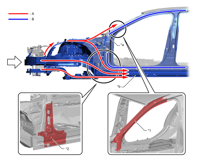
*1 Front Body Pillar Reinforcement UPR OUTER *2 Front Body Pillar Reinforcement LWR OUT *a Front Body Pillar *b Rocker
-
-
A front bumper reinforcement sub-assembly (*1 in illustration), which is highly resistant to warping, is used. It efficiently spreads impact energy received during a frontal collision to the opposite side of the vehicle and dissipates impact energy to body parts to increase the amount of impact energy that is absorbed in the engine compartment.
-
A wide crush box (front bumper mounting reinforce sub-assembly (*2 in illustration)) is used and a gusset (outrigger gusset No. 1 (*3 in illustration)) is provided to ensure superior initial collision energy absorption in various types of collisions.
Figure 3. Impact Absorbing Structure for Frontal Collision (The illustration shown is an example only.)
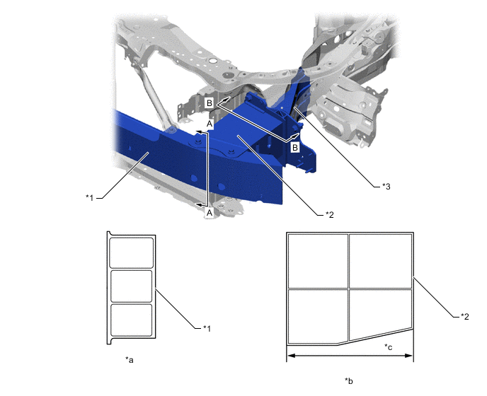
*1 Front Bumper Reinforcement Sub-assembly *2 Front Bumper Mounting Reinforce Sub-assembly LH *3 Outrigger Gusset No. 1 LH - - *a A - A Cross Section *b B - B Cross Section *c Wide Crush Box - -
-
-
Impact Absorbing Structure for Side Collision
-
Hot-stamped steel (tensile strength: 1500 MPa class), ultra high-tensile strength steel (tensile strength: 980 MPa class) and high-tensile strength steel (tensile strength: 590 MPa class) are used in the body frame, achieving weight reduction and structure simplification while ensuring strength.
-
Hot-stamped sheet steel is used for the center body pillar reinforcement UPR (*1 in illustration) and center body pillar reinforcement INNER (*2 in illustration), suppressing cabin deformation during side collisions and achieving weight reduction.
-
Adhesive is applied between the center body pillar reinforcement UPR (*1 in illustration) and center body pillar reinforcement INNER (*2 in illustration), achieving weight reduction.
-
The length of the upper and lower connections of the center body pillars is extended (*c in illustration) to increase the number of welding points and achieve connecting rigidity, dissipating the impact load to the rail on the top of the vehicle and the rocker at the bottom of the vehicle.
Figure 4. Impact Absorbing Structure for Side Collision (The illustration shown is an example only.)
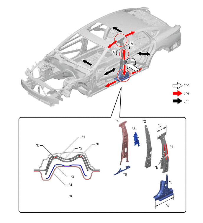
*1 Center Body Pillar Reinforcement UPR LH *2 Center Body Pillar Reinforcement INNER LH *3 Belt Anchor to Center Pillar Reinforcement LH *4 Center Body Pillar INNER LH *5 Center Body Pillar Reinforcement LWR LH *6 Center Body Pillar INNER LWR LH *a A - A Cross Section *b Structural Adhesive *c Upper and Lower Connection Range of Center Body Pillar *d Side Impact Energy *e Impact Energy Absorption Direction Greatly Affected by Reinforcement Effect *f Dissipate -
Hot-stamped sheet steel (1500 MPa tensile strength class) is used for the roof side rail (*1 in illustration) and front body pillar reinforce UPR OUTER (*2 in illustration), and ultra high strength sheet steel is used for the roof side rail INNER (*3 in illustration) and roof side rail INNER No. 2 (*4 in illustration). As a result, cabin deformation during side collisions is suppressed and weight reduction is achieved.
Figure 5. Impact Absorbing Structure for Side Collision (The illustration shown is an example only.)
*1 Roof Side Rail LH *2 Front Body Pillar Reinforce UPR OUTER LH *3 Roof Side Rail INNER *4 Roof Side Rail INNER No. 2 *5 Center Body Pillar Reinforcement UPR LH - - *a A - A Cross Section *b Side Impact Energy *c Impact Energy Absorption Direction Greatly Affected by Reinforcement Effect *d Dissipate -
Ultra high strength sheet steel (1180 MPa tensile strength class) is used for the floor side member INNER (*1 in illustration) and rocker panel OUTER (*2 in illustration), and high strength sheet steel (590 MPa tensile strength class) is used for the rocker reinforcement OUTER (*3 in illustration). As a result, cabin deformation during side collisions is suppressed and weight reduction is achieved.
-
The rocker panel reinforcement No. 3 (*4 in illustration), rocker panel reinforcement No. 4 (*5 in illustration) and front floor cross side member (*6 in illustration) are used for the inside of the rocker and the underbody below the center body pillar, achieving a structure that efficiently transmits input during side collisions to the side opposite the collision.
Figure 6. Impact Absorbing Structure for Side Collision (The illustration shown is an example only.)
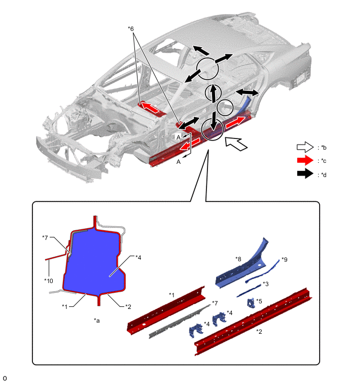
*1 Floor Side Member INNER LH *2 Rocker Panel OUTER LH *3 Rocker Reinforcement OUTER LH *4 Rocker Panel Reinforcement No. 3 *5 Rocker Panel Reinforcement No. 4 *6 Front Floor Cross Side Member *7 Front Floor Reinforcement No. 2 LH *8 Floor Side Member INNER RR LH *9 Floor Side Rail Plate LH *10 Front Floor Cross Member LH *a A - A Cross Section *b Side Impact Energy *c Impact Energy Absorption Direction Greatly Affected by Reinforcement Effect *d Dissipate -
The front door side impact protect beam No. 2 (*1 in illustration), door side-impact protect beam sub-assembly (*2 in illustration) and rear door side impact protection beam (*3 in illustration) are optimally positioned, achieving a structure that efficiently transmits impact load to the front and center body pillars. Also, the front door side impact protect beam No. 2 is provided next to the passenger's abdomen, reducing the level of injuries by suppressing door deformation during side collisions.
-
The rear door reinforcement No. 2 (*4 in illustration) is positioned below the rear door outside handle, suppressing deformation of the rear door panel OUTSIDE (*5 in illustration) around the outside handle during side collisions to reduce the level of injury.
Figure 7. Impact Absorbing Structure for Side Collision (The illustration shown is an example only.)
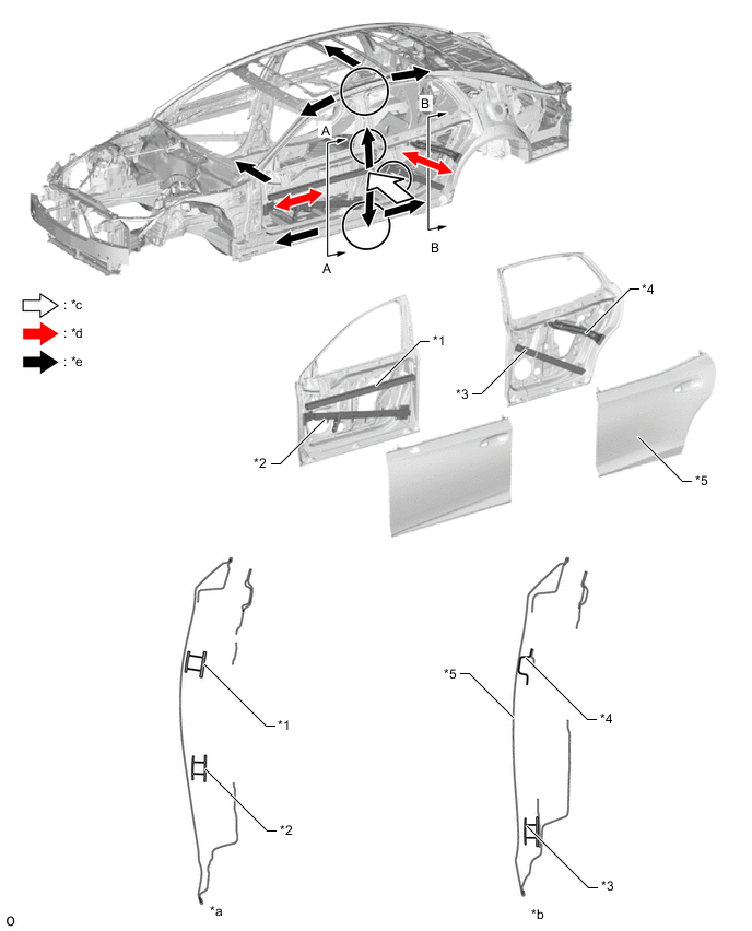
*1 Front Door Side Impact Protect Beam No. 2 LH *2 Door Side Impact Protect Beam Sub-assembly LH *3 Rear Door Side Impact Protection Beam LH *4 Rear Door Reinforcement No. 2 LH *5 Rear Door Panel OUTSIDE LH - - *a A - A Cross Section *b B - B Cross Section *c Side Impact Energy *d Impact Energy Absorption Direction Greatly Affected by Reinforcement Effect *e Dissipate - -
-
-
-
Impact Absorbing Structure for Rear Collision
-
(USA)
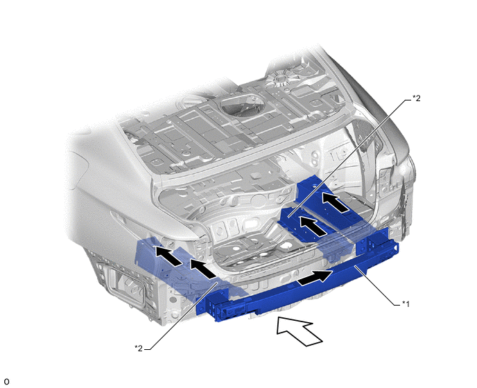
An aluminum rear bumper reinforcement sub-assembly with a high level of bending rigidity is used due to its unique bent shape and large size.
-
A light and rigid aluminum rear bumper reinforcement sub-assembly is used. Impact energy is dissipated to the left and right members during rear offset collisions, suppressing cabin deformation.
-
A rear floor side plate is provided to enhance resistance against rear body deformation, suppressing cabin deformation during rear collisions.
Figure 8. Impact Absorbing Structure for Rear Collision (Except models for Europe)
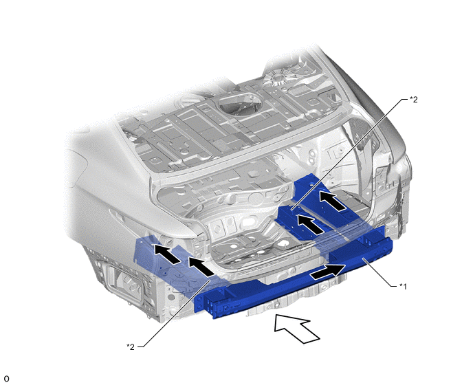
*1 Rear Bumper Reinforcement Sub-assembly *2 Rear Floor Side Plate Rear Impact Energy Dissipate Figure 9. Impact Absorbing Structure for Rear Collision (Models for Europe)
*1 Rear Bumper Reinforcement Sub-assembly *2 Rear Floor Side Plate Rear Impact Energy Dissipate
-
-
Roof Crush Resistance (Models with Sliding Roof)
-
A high strength sheet steel (440 MPa tensile strength class) windshield header panel OUTER (*1 in illustration) and high strength sheet steel (590 MPa tensile strength class) windshield header panel INNER (*2 in illustration) and front body pillar reinforcement UPR INNER (*3, *4 in illustration) are used for superior strength for the roof.
-
A high strength sheet steel (590 MPa tensile strength class) removable roof bracket reinforcement (*5, *6 in illustration) and hot-stamped sheet steel (1500 MPa tensile strength class) sliding roof housing frame sub-assembly No. 1 (*7 in illustration) are used to ensure superior roof strength.
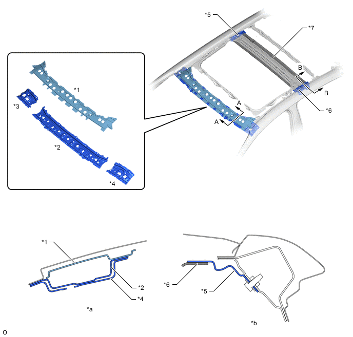
*1 Windshield Header Panel OUTER *2 Windshield Header Panel INNER *3 Front Body Pillar Reinforcement UPR INNER RH *4 Front Body Pillar Reinforcement UPR INNER LH *5 Removable Roof Bracket Reinforcement RH *6 Removable Roof Bracket Reinforcement LH *7 Sliding Roof Housing Frame Sub-assembly No. 1 - - *a A - A Cross Section *b B - B Cross Section
-
-
Reduction Pedestrian Leg Injury
-
The front bumper energy absorber sub-assembly is provided in front of the front bumper reinforcement sub-assembly and the radiator support opening cover is provided under the radiator grille, achieving a structure that reduces impact to the pedestrian's lower legs. In addition, an energy absorbing structure is used for the area that contacts the pedestrian's thighs in consideration of pedestrian protection.
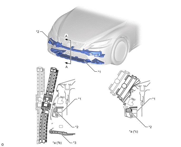
*1 Front Bumper Reinforcement Sub-assembly *2 Front Bumper Energy Absorber Sub-assembly *3 Radiator Support Opening Cover - - *a A - A Cross Section *b Leg Part Protection Structure *c Thigh Part Protection Structure - -
-
-