LIGHTING SYSTEM
-
CONSTRUCTION
-
LED Headlights
-
Through optimization of the shape of the lenses and reflectors inside the lights, a large illumination range has been achieved.
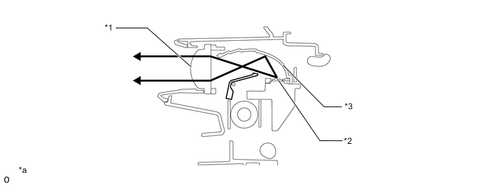
*1 Lens *2 Reflector *3 LED - - *a The illustration is for high beams. - -
-
-
Bi-function
-
When low beam is selected, the light source of the high beam headlight is blocked by the shade in the headlight assembly.
-
When high beam is selected, the shade turns so the light source of the high beam is not blocked.
-
The bi-function is activated by the headlight ECU sub-assembly. The headlight ECU sub-assembly receives as signal to turn on the high beams from the headlight dimmer switch assembly, then activates the built-in headlight actuator to slide the shade down.
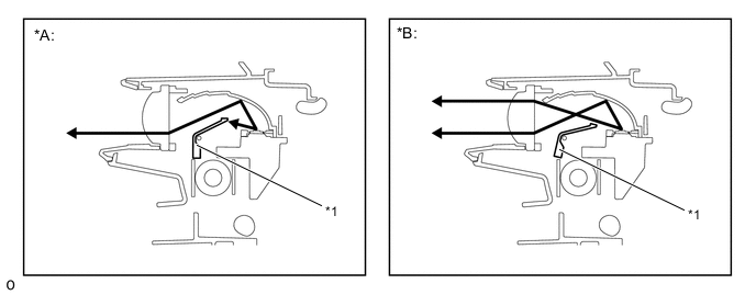
*A Low Beam *B High Beam *1 Shade - -
-
-
LED Unit Structure for Adaptive High Beam System (Models with Adaptive High Beam System)
-
An LED unit is provided for the adaptive high beam system.
-
24 LED chips for the adaptive high beam system are used to form light distribution patterns
-
8 LED units for the adaptive high beam system are used for the upper row and 16 LED chips are used for the lower row.
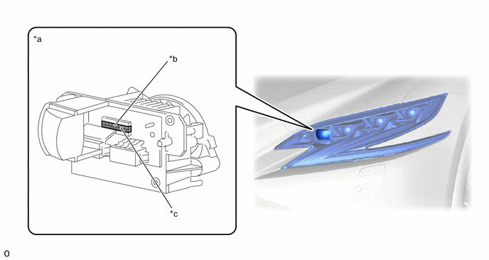
*a LED Unit for Adaptive High Beam System (AHS) *b LED chips (Upper Row) *c LED chips (Lower Row) - -
-
-
-
OPERATION
-
LED Unit Structure for Adaptive High Beam System (Models with Adaptive High Beam System)
-
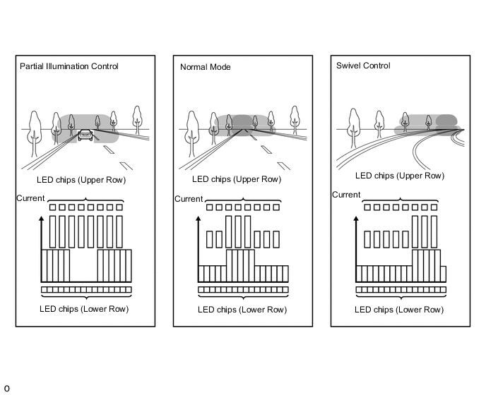
24 LED chips are positioned in the LED unit for the adaptive high beam system and they are operated by the LED light control ECU.
-
By adjusting the brightness of each LED using pulse width modulation, it is possible to optimally control the illumination area of the high beams.
-
-