BLIND SPOT MONITOR SYSTEM
-
FUNCTION OF MAIN COMPONENTS
Component Function Blind Spot Monitor Sensor LH/RH
-
Outputs radar from the blind spot monitor sensor to the blind spot sensor detection area, uses the reflected radar for detecting the presence of a vehicle, the vehicle-to-vehicle distance, and the relative speed, and then sends this information to the built-in signal processing circuit.
-
The signal processing circuit determines if a vehicle is present, and illuminates or blinks the outer rear view mirror indicator light accordingly.
-
Receives display dimmer signals from the main body ECU and dims the outer rear view mirror indicator light.
Outer Rear View Mirror Assembly LH/RH
-
Outer Rear View Mirror Indicator Light
-
Illuminates to inform the driver that a vehicle has been detected in the blind spot monitor sensor detection area.
-
Flashes to inform the driver when the turn signal lever is operated if a vehicle has been detected in the blind spot monitor sensor detection area.
Combination Meter Assembly
-
BSM Indicator
-
Multi-information Display
-
Master Warning Indicator
-
Meter Buzzer
-
Sends the on/off signal of the BSM system to the blind spot monitor sensor RH.
-
Sends the turn light signal to the blind spot monitor sensor RH.
-
Illuminates the BSM indicator to inform the driver when the BSM system is on.
-
When a malfunction is detected in the blind spot monitor sensors or the blind spot monitor sensors determine that control is not possible, the master warning indicator illuminates and a message is displayed on the multi-information display to warn the driver.
-
Sends the customization information signal of the BSM system to the blind spot monitor sensor RH.
-
Sounds to warn the driver of a malfunction in the blind spot monitor system.
Turn Signal Switch Sends the turn light signal to the steering sensor. Steering Sensor
-
Sends the steering angle signal to the blind spot monitor sensor RH.
-
Sends the turn light signal to the combination meter assembly.
Yawrate Sensor Sends yawrate information to the blind spot monitor sensor RH. Hybrid Vehicle Control ECU Assembly Sends the shift position signal to the blind spot monitor sensor RH. Skid Control ECU Assembly Sends the vehicle speed signal to the blind spot monitor sensor RH. Main Body ECU (Multiplex Network Body ECU) Sends display dimmer signals to the blind spot monitor sensor RH. Central Gateway ECU (Network Gateway ECU) Relays the signal between the CAN communication buses. DLC3
-
The Global TechStream (GTS) can be connected to read the Diagnostic Trouble Codes (DTCs) of malfunctions.
-
The Global TechStream (GTS) can be connected to change settings as desired by the user.
-
-
OPERATING CONDITION
-
The BSM system operates when all of the following conditions are met:
-
The BSM system is on.
-
The shift position is other than R.
-
The vehicle speed is greater than approximately 16 km/h (10 mph).
-
-
-
SYSTEM CONTROL
-
The BSM system can detect vehicles in its detection areas.
-
The detection areas formed by the blind spot monitor sensor LH and RH are as shown below.
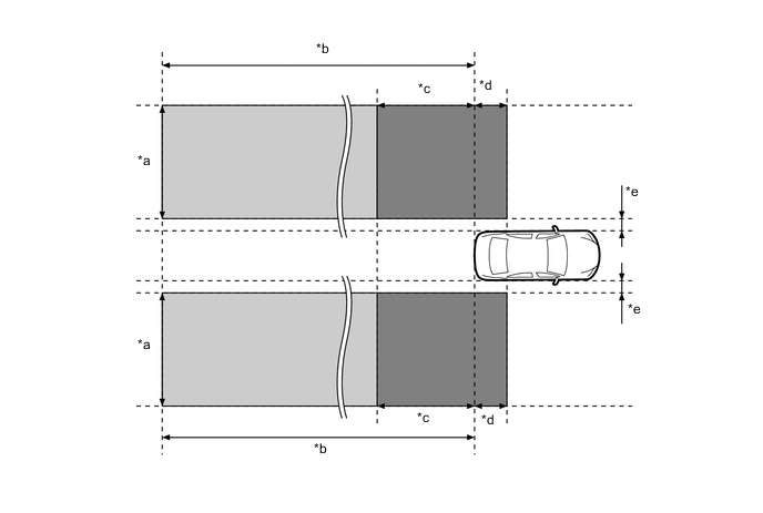
*a Approximately 3.0 m (9.8 ft.) *b Approximately 60 m (197 ft.) *c Approximately 3.0 m (9.8 ft.) *d Approximately 1.0 m (3.3 ft.) *e Approximately 0.5 m (1.6 ft.) - - 
Detection Area (for Vehicle in Blind Spot) 
Detection Area (for Rapidly Approaching Vehicle from Behind) Tech Tips
If another vehicle that is rapidly approaching the vehicle's blind spot is detected, the notification timing is determined by the relative speed of the approaching vehicle. The notification timing for vehicles rapidly approaching the vehicle's blind spot can be customized. For details, refer to the Repair Manual.
-
Detection Area (for Vehicle in Blind Spot)
-
When this vehicle is overtaken by another vehicle in an adjacent lane.
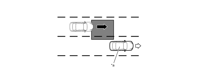
*a This Vehicle - - 
Vehicle Speed (Fast) 
Vehicle Speed (Slow) Detection Area - - -
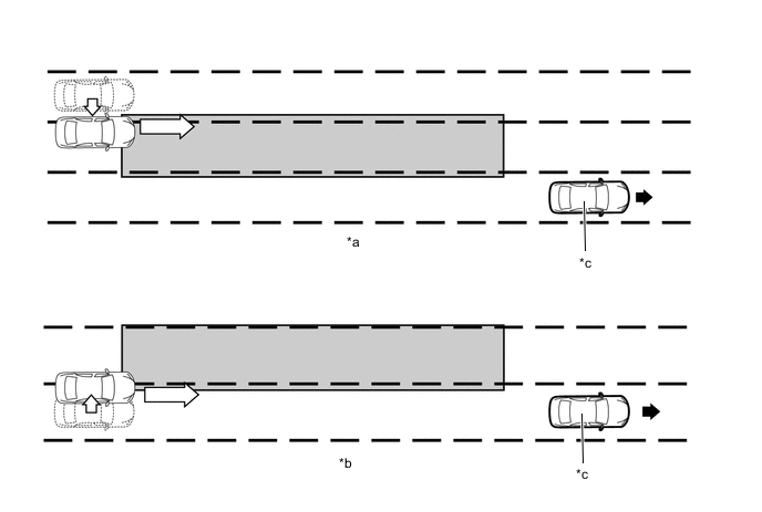
When another vehicle enters the detection area of this vehicle due to a lane change.
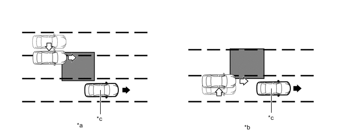
*a Another vehicle enters the detection area during lane change (merge in) (Type 1). *b Another vehicle enters the detection area during lane change (merge in) (Type 2). *c This Vehicle - - Motion Direction of This Vehicle Motion Direction of Another Vehicle Detection Area - -
-
-
Detection Area (for Rapidly Approaching Vehicle from Behind)
-
When another vehicle is rapidly approaching from behind.
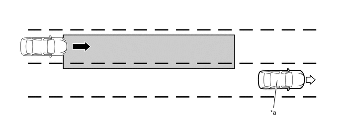
*a This Vehicle - - Vehicle Speed (Fast) Vehicle Speed (Slow) Detection Area - - -
When another vehicle enters the detection area of this vehicle due to a lane change and approaches this vehicle.
*a Another vehicle enters the detection area during lane change (merge in) (Type 1). *b Another vehicle enters the detection area during lane change (merge in) (Type 2). *c This Vehicle - - Motion Direction of This Vehicle Motion Direction of Another Vehicle Detection Area - -
-
-
According to operation conditions, the BSM system promotes safety confirmation by using the outer rear view mirror indicator light to inform the driver that the system detects vehicles that are in the vehicle's blind spot.
-
The outer rear view mirror indicator light illuminates when a vehicle is in or rapidly approaching the vehicle's blind spot and the turn light switch is not operated. The indicator light flashes when a vehicle is in or rapidly approaching the vehicle's blind spot and the turn light switch is operated.
-
-
-
FUNCTION
-
Blind Spot Monitor System Operation
-
The combination meter assembly customization setting can be used to turn BSM system on and off.
-
The BSM indicator that can be used to check whether the BSM system is on or off is positioned in the combination meter assembly. When the BSM system is on, the indicator illuminates, and when the BSM system is off, the indicator light turns off, indicating the operation status.
-
The combination meter assembly customization setting can be used to change the brightness of the outer rear view mirror indicator light and the BSM system detection timing.
-
-
Customization Function
-
Settings of some functions can be changed as desired by the user. Refer to the Repair Manual for details.
-
-
-
DIAGNOSIS
-
In order to make system inspections easier to perform, a diagnosis function is used in consideration of serviceability. The DTCs of malfunctioning parts can be read by connecting the Global TechStream (GTS). Refer to the Repair Manual for details.
-