PARKING SUPPORT BRAKE SYSTEM
-
FUNCTION OF MAIN COMPONENTS
Component Function Front Corner Ultrasonic Sensor RH/LH Sends ultrasonic waves to detect stationary objects and outputs a signal to the clearance warning ECU assembly. Front Center Ultrasonic Sensor RH/LH Rear Corner Ultrasonic Sensor RH/LH Rear Center Ultrasonic Sensor RH/LH Blind Spot Monitor Sensor RH/LH*1 Sends a vehicle behind approaching detection signal to the clearance warning ECU assembly. Television Camera Assembly*2 Sends a pedestrian behind detection signal to the clearance warning ECU assembly. Clearance Warning ECU Assembly
-
Receives information regarding to an stationary object, etc. in the vehicle traveling direction detected by the ultrasonic sensor, a vehicle approaching the driver's own vehicle from behind detected by the blind spot monitor sensor, and a pedestrian behind the vehicle detected by the television camera, and judges the vehicle condition based on signals from sensors, switches and ECUs located various places to perform parking support brake system control.
-
Sends a parking support brake system control signal to the hybrid vehicle control ECU assembly and skid control ECU assembly.
-
Sends a parking support brake system control status signal, warning request signal and malfunction judgment signal to the combination meter assembly.
-
Sends a parking support brake system warning request signal to the parking assist ECU.*2
-
Sends a parking support brake system warning request signal to the headup display.*3
Combination Meter Assembly
-
PKSB OFF Indicator
-
Multi-information Display
-
Master Warning Indicator
-
Sends a parking support brake system on/off signal to the clearance warning ECU assembly.
-
Receives a control status signal, warning request signal and combination meter assembly malfunction judgment signal from the clearance warning ECU assembly and displays a message on the multi-information display.
-
Illuminates the PKSB OFF indicator when the parking support system is off.
-
Sends a vehicle speed signal to the clearance warning ECU assembly.
-
Sends a customization signal to the clearance warning ECU assembly.
Multi-display Receives a warning request signal from the parking assist ECU and displays a parking support brake system warning message.*2 Headup Display (Meter Mirror Sub-assembly)*3 Receives a warning request signal from the clearance warning ECU assembly and displays a parking support brake system warning message. Hybrid Vehicle Control ECU Assembly
-
Sends a shift position signal, accelerator pedal depression amount signal, etc. to the clearance warning ECU assembly.
-
Performs drive force suppression control in response to a parking support brake system control signal received from the clearance warning ECU assembly.
Skid Control ECU Assembly
-
Sends wheel speed information, a brake pedal status signal and a master cylinder pressure signal to the clearance warning ECU assembly.
-
Performs brake control in response to a parking support brake system control signal received from the clearance warning ECU assembly.
Parking Assist ECU*2 Sends a warning request signal received from the clearance warning ECU assembly to the multi-display. Yawrate Sensor Sends a lateral acceleration signal, which was detected by the yawrate sensor, to the clearance warning ECU assembly. Steering Sensor Sends a steering angle signal to the clearance warning ECU assembly. Air Conditioning Amplifier Assembly Sends an outside temperature signal to the clearance warning ECU assembly. Central Gateway ECU (Network Gateway ECU) Relays the signal between the CAN communication buses. DLC3
-
The Global TechStream (GTS) can be connected to read the Diagnostic Trouble Codes (DTCs) of malfunctions.
-
The Global TechStream (GTS) can be connected to change settings as desired by the user.
*1: Models with blind spot monitor system
*2: Models with panoramic view monitor system
*3: Models with headup display
-
-
OPERATING CONDITION
-
Drive Force Suppression Control
-
When all of the following conditions are met, drive force suppression control is performed.
Detectable Item Condition Stationary Object
-
The power switch is on (IG).
-
The parking support brake system is on.
-
An stationary object is in the traveling direction of the driver's own vehicle.
-
The vehicle speed is 15 km/h (9 mph) or less.
-
The driver can avoid the object by braking operations.
Vehicle Approaching from Rear*1
-
The power switch is on (IG).
-
The parking support brake system is on.
-
The shift position is R.
-
The vehicle speed is 15 km/h (9 mph) or less.
-
An approaching vehicle may collide with the driver's own vehicle.
Pedestrian behind Vehicle*2
-
The power switch is on (IG).
-
The parking support brake system is on.
-
The shift position is R.
-
The vehicle speed is 15 km/h (9 mph) or less.
-
There is a possibility that the driver's own vehicle may collide with a pedestrian behind.
*1: Models with blind spot monitor system
*2: Models with panoramic view monitor system
-
-
When any of the following conditions is met, drive force suppression control is stopped.
Detectable Item Condition Stationary Object
-
The power switch is off.
-
The parking support brake system is off.
-
Collision is avoided.
-
An stationary object moves or is moved away from the traveling direction of the driver's own vehicle.
Vehicle Approaching from Rear*1
-
The power switch is off.
-
The parking support brake system is off.
-
Collision is avoided.
-
A vehicle, which was approaching the driver's vehicle from behind, has moved away.
Pedestrian behind Vehicle*2
-
The power switch is off.
-
The parking support brake system is off.
-
Collision is avoided.
-
A pedestrian behind the vehicle has gone away.
*1: Models with blind spot monitor system
*2: Models with panoramic view monitor system
-
-
-
Brake Control
-
When all of the following conditions are met, brake control is performed.
Detectable Item Condition All Objects
-
Drive force suppression control is in operation.
-
Collision is difficult to avoid by braking by the driver.
-
-
When the following conditions are met, brake control is stopped.
Detectable Item Condition Stationary Object
-
The power switch is off.
-
The parking support brake system is off.
-
An stationary object moves or is moved away from the traveling direction of the driver's own vehicle.
-
The driver depresses the brake pedal after the vehicle is stopped by brake control.
-
Approximately 2 seconds have elapsed since the vehicle is stopped by brake control.
Vehicle Approaching from Rear*1
-
The power switch is off.
-
The parking support brake system is off.
-
A vehicle, which was approaching the driver's vehicle from behind, has moved away.
-
The driver depresses the brake pedal after the vehicle is stopped by brake control.
-
Approximately 2 seconds have elapsed since the vehicle is stopped by brake control.
Pedestrian behind Vehicle*2
-
The power switch is off.
-
The parking support brake system is off.
-
A pedestrian behind the vehicle has gone away.
-
The driver depresses the brake pedal after the vehicle is stopped by brake control.
-
Approximately 2 seconds have elapsed since the vehicle is stopped by brake control.
*1: Models with blind spot monitor system
*2: Models with panoramic view monitor system
Note
When brake control operates, the parking support brake system automatically turns off. The system remains off until it is turned on by an operation on the multi-information display screen, the object of brake control goes away, the vehicle reverses approximately 300 mm (11.8 in.) or more*1 or approximately the entire length of the vehicle*2, the vehicle moves forward approximately the entire length of the vehicle*3, or the power switch is turned off and back on (IG).
-
*1: A vehicle approaching from the rear is detected.
*2: A stationary object or pedestrian who is behind the vehicle is detected.
*3: A stationary object is detected.
-
-
-
-
SYSTEM CONTROL
-
Parking Support Brake (Stationary Objects) Detection Range
-
The ultrasonic sensor detects stationary objects that come within approximately 4 m (13 ft.). In addition, the detection distance may differ depending on the shape of the stationary object.
-
When the vehicle is moving forward, all 4 front ultrasonic sensors must simultaneously detect an obstacle for the parking support brake system to operate. Similarly, when the vehicle is moving in reverse, 2 or more rear ultrasonic sensors must detect a stationary object for the system to operate.
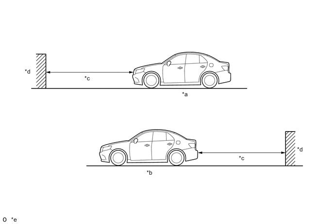
*a While Driving Ahead *b While Reversing *c Approximately 4 m (13 ft.) *d Object *e The detection range shown in the illustration is for when detecting an object that is 2 m (6.7 ft.) wide, 1 m (3.3 ft.) tall and is perpendicular to the ground. - - Note
Even though the parking support brake system detects stationary objects, it may not operate depending on the vehicle condition.
-
-
Parking Support Brake System Control
-
The parking support brake system determines the state of the vehicle and its surroundings based on signals that the clearance warning ECU assembly receives from sensors, switches and ECUs installed in various locations on the vehicle, and sends the necessary control signals to ECUs to control the vehicle.
-
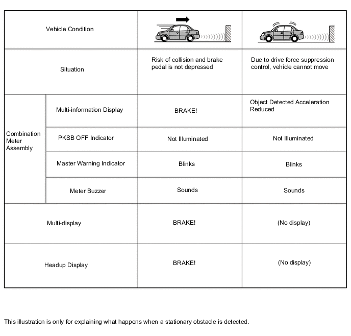
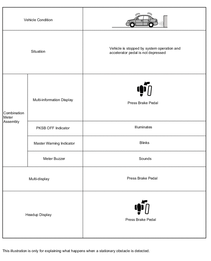
When the system operates, a warning message is displayed in the multi-information display of the combination meter assembly, multi-display or headup display*, and the meter buzzer sounds to warn the driver.
-
*: Models with headup display
-
-
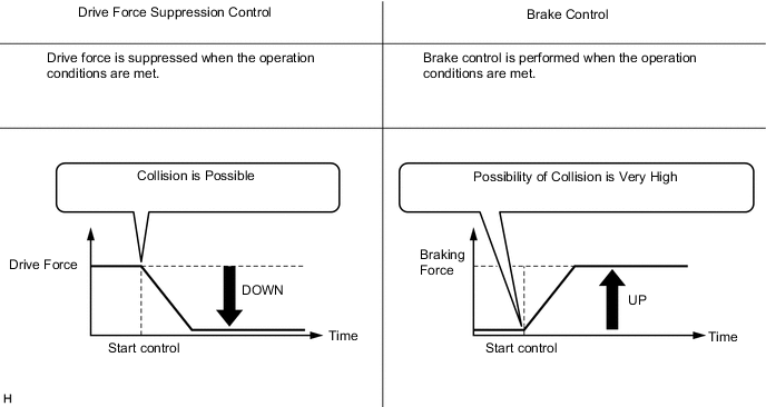
The parking support brake system detects stationary objects using sensors, and when it determines that there is a risk of collision, suppress the drive force.
Figure 1. Drive Force Suppression Control
-
When the system determines that there is a high possibility of a collision even after the above operations, brake control is performed in addition to drive force suppression control.
Figure 2. Drive Force Suppression Control and Brake Control 1
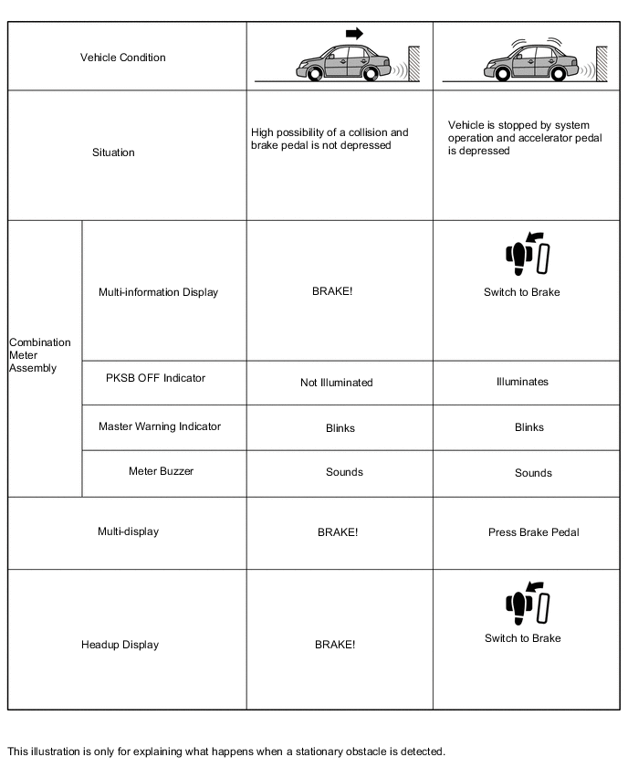
Figure 3. Drive Force Suppression Control and Brake Control 2
-
-
-
FUNCTION
-
Parking Support Brake System Operation
-
The combination meter assembly customization setting can be used to turn the parking support brake system on and off.
-
A PKSB OFF indicator is added to make it possible to check that the parking support brake system is off in the combination meter assembly. When the parking support brake system is off, the PKSB OFF indicator illuminates.
-
-
-
FAIL-SAFE
-
When the clearance warning ECU assembly detects a malfunction in the system, the system enters fail-safe mode. For details, refer to the Repair Manual.
-
-
DIAGNOSIS
-
In order to make system inspections easier to perform, a diagnosis function is used in consideration of serviceability. The DTCs of malfunctioning parts can be read by connecting the Global TechStream (GTS). Refer to the Repair Manual for details.
-