POWER INTEGRATION SYSTEM
-
FUNCTION OF MAIN COMPONENTS
Components Function No. 1 Semiconductor Power Integration ECU
-
Receives signals from ECUs and switches, and then drives each component.
-
Shuts off current when a malfunction occurs.
-
Performs multiplex communication with the DLC3 and ECUs.
No. 2 Semiconductor Power Integration ECU No. 3 Semiconductor Power Integration ECU Heater Water Pump (Heater Accessory Assembly) Circulates coolant to ensure a stable heat source for the heater during idling stop control. PTC Heater (Quick Heater Assembly)* Generates heat when current is applied, warming the air. Stop Light Illuminates when the brakes operate. Center Stop Light Assembly Back-up Light Illuminates when the shift position is in R. Taillight
-
Illuminates according to certain conditions when the light control switch is in the TAIL, HEAD or AUTO position.
-
Illuminates when the welcome light illumination operates.
License Plate Light Assembly Rear Fog Light Illuminates when the rear fog switch is turned on. Rear Window Defogger Wire Generates heat when current is applied, warming the back window. Stop Light Switch Assembly Detects the brake pedal condition (on or off) and outputs it to the No. 3 semiconductor power integration ECU. Shift Control ECU
-
Controls the electronic shift lever system.
-
Outputs reverse signals to the No. 3 semiconductor power integration ECU.
Skid Control ECU Assembly
-
Controls the electronically controlled brake system.
-
Sends brake light operation requests to the main body ECU.
Main Body ECU (Multiplex Network Body ECU)
-
Controls the body control systems.
-
Receives component operation requests and sends them to the semiconductor power integration ECUs.
Air Conditioning Amplifier Assembly
-
Controls the air conditioning system.
-
Sends rear window defogger, heater water pump and PTC heater* operation request signals to the main body ECU.
Headlight ECU Sub-assembly LH
-
Controls the headlight system.
-
Receives operation request signals from the No. 1 semiconductor power integration ECU and outputs illumination command signals to the headlights.
Headlight ECU Sub-assembly RH Steering Sensor Outputs headlight dimmer switch assembly signals to the main body ECU. Central Gateway ECU (Network Gateway ECU) Relays the signal between the CAN communication lines. DLC3 Connects to the Global TechStream (GTS). *: Models with PTC heater
-
-
FUNCTION
Communication Support of Semiconductor Power Integration ECU Components Semiconductor Power Integration ECU Operation Signal Communication Support No. 1 No. 2* No. 3 Headlight ECU Sub-assembly LH ○ X X X Headlight ECU Sub-assembly RH ○ X X X Heater Water Pump Assembly (Heater Accessory Assembly) ○ X X ○ PTC Heater (Quick Heater Assembly)* X ○ X ○ Stop Light
Center Stop Light Assembly
X X ○ X Back-up Light X X ○ X Taillight
License Plate Light Assembly
X X ○ ○ Rear Fog Light X X ○ ○ Rear Window Defogger Wire X X ○ ○ Tech Tips
*: Models with PTC heater
○: Supported
X: Not supported
-
Component Operation Output Function
-
This function turns the corresponding component on and off in accordance with operation signals or switch input signals from the ECU.
-
-
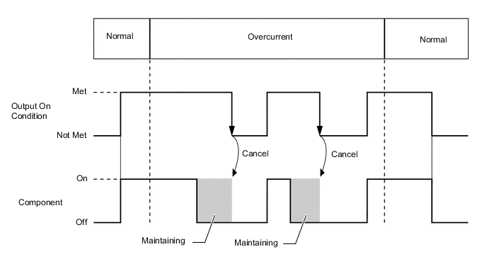
Semiconductor Fuse Function
-
When an abnormal electric current occurs during operation of components, the components are turned off by shutting off the current before electrical wire emits smoke.
-
The electrical current is maintained shut off while operation signals or switch signals are on.
-
When operation signals or switch signals are turned off, the shut off condition is canceled.
-
-
Multiplex Communication Function
-
Operation Signal Communication
-
This communication uses the multiplex communication line (CXPI communication line) to input operation signals or switch signals from the ECU.
-
-
Diagnosis Communication
-
Checking Diagnostic Trouble Codes (DTCs) regarding ECU and other malfunctions is possible by connecting the Global TechStream (GTS).
-
The semiconductor fuse condition (shut off or not) can be confirmed by connecting the Global TechStream (GTS).
-
-
Reprogramming
-
Reprogramming can be performed by connecting the Global TechStream (GTS).
Tech Tips
Refer to the Repair Manual for the details of the diagnostic communication and reprogramming.
-
-
-
-
DIAGNOSIS
-
In order to make system inspections easier to perform, a diagnosis function is used in consideration of serviceability. The Diagnostic Trouble Codes (DTCs) of malfunctions can be read by connecting the Global TechStream (GTS). For details, refer to the Repair Manual.
-