ELECTRONIC SHIFT LEVER SYSTEM
-
FUNCTION OF MAIN COMPONENTS
Component Function Shift Control ECU
-
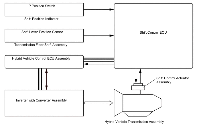
Performs shift control for each shift position based on signals from the shift lever position sensor, P position switch and various ECUs and sends control signals to the hybrid vehicle control ECU assembly.
-
Operates the parking lock motor inside the shift control actuator assembly based on P position switch operation signals and the vehicle condition.
Hybrid Vehicle Control ECU Assembly Receives control signals from the shift control ECU and controls the hybrid vehicle transmission. Certification ECU (Smart Key ECU Assembly) Receives shift position signals from the shift control ECU and outputs hybrid system start permission signals to the hybrid vehicle control ECU assembly. Skid Control ECU Assembly Sends the vehicle speed signal to the shift control ECU. Central Gateway ECU (Network Gateway ECU) Relays and transmits each CAN communication data signal. No. 3 Semiconductor Power Integration ECU Receives shift position signals from the shift control ECU and illuminates the back-up light. No. 1 Engine Room Relay Block P CON MTR Relay Turns on according to signals from the shift control ECU and supplies power from the auxiliary battery to the parking lock motor inside the shift control actuator assembly. IGCT No. 1 Relay Turns on according to signals from the hybrid vehicle control ECU assembly and supplies power from the auxiliary battery to the shift control ECU. No. 2 Luggage Room Relay Block P CON MTR 2 Relay Turns on according to signals from the shift control ECU when the auxiliary battery voltage drops and supplies power from the sub-battery with control assembly to the parking lock motor inside the shift control actuator assembly. Sub-battery with Control Assembly Supplies power to the shift control ECU and the parking lock motor inside the shift control actuator assembly when the auxiliary battery voltage drops. Auxiliary Battery Supplies power to the shift control ECU and the parking lock motor inside the shift control actuator assembly. Stop Light Switch Assembly Detects the depressing of the brake pedal and transmits a signal to the shift control ECU. Transmission Floor Shift Assembly Shift Lever Position Sensor Detects the shift positions (Home, R, N, D or M), and transmits the shift position signal to the shift control ECU. Shift Position Indicator Indicator Illuminates the shift position (R, N. D or M). P Position Switch
-
Detects the driver's operation of the parking lock, and sends it to the shift control ECU.
-
Informs the driver that the shift position is P by illuminating the light.
Combination Meter Assembly Shift Position Indicator Indicates the shift position (P, R, N, D or M). Multi-information Display Shows a message to warn the driver when a system malfunction occurs or the reject function operates. Master Warning Light
-
Illuminates to warn the driver when a system malfunction occurs.
-
Flashes to warn the driver when the reject function operates.
Buzzer
-
Continuously sounds to warn the driver when the accelerator pedal is depressed with the shift position in N and the power switch on (READY).
-
Sounds to warn the driver when a system malfunction occurs or the reject function operates.
Meter Mirror Sub-assembly* Displays the shift position. Shift Control Actuator Assembly Parking Lock Motor Engages or disengages the transmission parking lock mechanism. Rotation Angle Sensor Detects the rotation angle of the rotor in the parking lock motor. Range Sensor Detects the lock or unlock of the transmission parking lock mechanism. *: Models with headup display
-
-
SYSTEM CONTROL
-
The shift control ECU sends requests to the hybrid vehicle control ECU assembly to switch to a shift range according to each shift position based on the shift lever position sensor signals and vehicle condition.
-
The shift control ECU operates the parking lock motor inside the shift control actuator assembly based on P position switch operation signals and the vehicle condition to lock and unlock the transmission parking lock mechanism.
-
-
FUNCTION
-
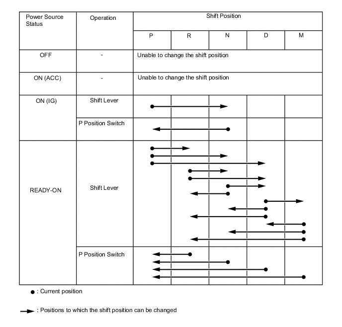
Shift Position Change Function
-
This system uses the shift control ECU to comprehensively determine driver operations and the vehicle condition to switch the shift position so that the driver can comfortably perform operations.
-
An "automatic P position switching function" is provided. When the power switch (push start switch) is turned off while the vehicle is stopped and the shift position is not P, the P position is automatically shifted to before switching the power source mode to off.
Note
While towing with the power switch on (IG), do not switch the power source mode to off. The automatic P position switching function may operate and secure the driving wheels with the transmission parking lock mechanism.
Tech Tips
-
If the hybrid system unavoidably stops while driving with the power source mode on (ACC) and the shift position in N, the P position is automatically shifted to when the vehicle stops.
-
When the auxiliary battery voltage drops while the shift position is not P, the shift position may automatically switch to P.
-
-
The shift position can be shifted to N while driving at or above a fixed speed even when the shift lever is not held in the N position. At this time, the buzzer in the combination meter assembly sounds and the master warning light illuminates. Also, a warning message is displayed on the multi-information display.
-
-
Reject Function
-
A reject function is provided to ensure safety.
-
When the following reject function target operations are performed, the shift position does not switch and the current shift position is maintained, or the system shifts to the N position. At this time, the buzzer in the combination meter assembly sounds, the master warning light illuminates and a warning message is displayed on the multi-information display to warn the driver according to each reject function target operation.
Reject Function Target Operation Shift Position After Reject Function Operation Multi-information Display Message Coping Process Shift operation from P position to other position or other position to P position performed repeatedly in short period of time P Shifting Unavailable
Wait a Moment and
Shift Again
Wait for short while, and then perform shift operation Shift operation from P or N position to M position Maintains current shift position Vehicle Must be in [D]
to Shift Into [M]
After switching shift position to D position, shift to M position Shift operation to R, D or M position with power switch on (IG) and READY indicator light turned off Maintains current shift position (P or N) Hybrid System Must be READY
to Shift
-
Turn power switch on (READY), and then perform shift operation to R, D or M position
-
Switch to D position, and then perform shift operation to M position
Shift operation from P position to other position with READY indicator light flashing P Shift operation from P position to other position with brake pedal released P Depress Brake to Shift Depress brake pedal before performing shift operation Shift operation from R position directly to M position N Shifted Into [N]
Vehicle Must be in [D]
to Shift Into [M]
Switch to D position, and then perform shift operation to M position Shift operation to D position while reversing N Shifted Into [N]
Vehicle Must be Stopped
to Shift Into [D]
Stop vehicle, and then perform shift operation Shift operation to R position while driving ahead N Shifted Into [N]
Vehicle Must be Stopped
to Shift Into [R]
Stop vehicle, and then perform shift operation Pressing and holding P position switch during driving or consecutive P position switch operation N Shifted Into [N]
Vehicle Must be Stopped
to Shift Into [P]
Completely stop vehicle, and then perform switch operation Shift operation from P position to other position with accelerator pedal and brake pedal both depressed P Release Accelerator to Shift Release accelerator pedal, and then perform shift operation while depressing brake pedal Shift operation to N position without holding shift lever in N Maintains current shift position Temporarily Hold Shift Lever
in [N] Position
to Shift Into [N]
When shifting to N position, hold shift lever in N for short while* Tech Tips
*: The system can switch to the N position when the shift lever is not held in N only when driving at a fixed speed or more.
-
-
-
Shift Position Indicator
-
A shift position indicator integrated with the P position switch is provided near the shift lever. The current shift position is displayed by illuminating a light.
-
A shift position indicator is provided in the combination meter assembly. The current shift position and possible shift positions are displayed. The normal operation method for shifting to the M position is to shift from the D position. Therefore, when a shift position other than D or M is selected, the shift pattern for shifting to the M position is not displayed. Also, when the READY indicator light is off with the power switch on (IG), the shift pattern for shifting to the R, D or M position is not displayed.
Figure 1. Shift Position Indicator Integrated with P Position Switch
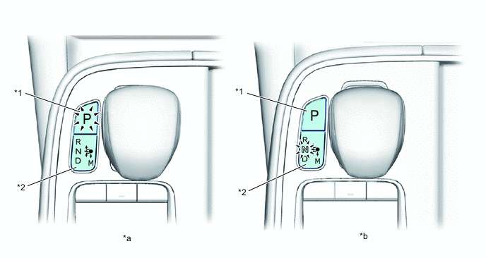
*1 P Position Switch *2 Shift Position Indicator *a P Position Selected
-
Switch Illuminates
*b N Position Selected
-
N Illuminates
Figure 2. Shift Position Indicator in Combination Meter Assembly
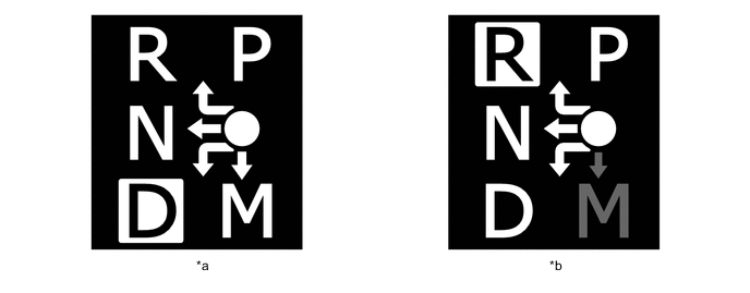
*a D Position Selected *b R Position Selected -
-
-
Shift Related Components Malfunction Display
-
When a malfunction occurs in the system or shift-related components, the buzzer in the combination meter assembly sounds, the master warning light illuminates and a warning message is displayed in the multi-information display to warn the driver.
Multi-information Display Function Constraint or Action to be Taken Shift System Malfunction
Apply Parking Brake Securely When Parking
See Owner's Manual
-
The transmission parking lock mechanism may not operate. When parking, select a flat area and securely apply the parking brake.
-
The hybrid system may not start.
-
When turning the power switch (push start switch) off, the system may remain on (ACC). At this time, when the parking brake is applied, it may be possible to switch from on (ACC) to off.
-
The automatic P position switching function may not operate. Before turning the power switch (push start switch) off, operate the P position switch and check that the shift position indicator indicates that the shift position is P.
Shift System Malfunction
See Owner's Manual
The system may not operate normally when left alone, which may be dangerous or cause a malfunction Shift System Malfunction
Stop in a Safe Place
See Owner's Manual
It may not be possible to switch the shift position. Park in a safe area. [P] Switch Malfunction
Apply Parking Brake Securely When Parking
See Owner's Manual
It may not be possible to switch the shift position to P even by operating the P position switch. When parking, select a flat area and securely apply the parking brake. Shift System Unavailable
Apply Parking Brake Securely When Parking
See Owner's Manual
-
The transmission parking lock mechanism may not operate. When parking, select a flat area and securely apply the parking brake.
-
The hybrid system may not start.
-
When turning the power switch (push start switch) off, the system may remain on (ACC). At this time, when the parking brake is applied, it may be possible to switch from on (ACC) to off.
Stop Vehicle in a Safe Place
Push [P] Switch
-
The automatic P position switching function may not operate. When parking, make sure to securely operate the P position switch.
-
This warning message is displayed when the auxiliary battery voltage drops. When parking, make sure to securely operate the P position switch.
Shift System Malfunction
Shifting Unavailable
Drive to a Safe Place and Stop
-
The shift position does not switch from D.
-
Drive to a safe area and park.
-
Slow acceleration may occur.
-
When the vehicle speed drops, driving may not be possible.
Shift System Malfunction
Driving Unavailable
Driving is not possible. Sub-Battery System Malfunction
Visit Your Dealer
When the vehicle is left alone and the battery is depleted, it may not be possible to switch to the P position. -
-
-
-
FAIL-SAFE
-
The electronic shift lever system has a fail-safe function which operates if a malfunction occurs. In this situation, the master warning light in the combination meter assembly illuminates, the buzzer sounds, and a warning message is displayed to inform the driver of a malfunction in the system.
-
-
DIAGNOSIS
-
When the shift control ECU detects a malfunction in the electronic shift lever system, the hybrid vehicle control ECU performs a diagnosis and memorizes the failed section. At the same time, the Diagnostic Trouble Code (DTC) is stored in its memory.
-
The DTC can be read by connecting the Global TechStream (GTS) to the DLC3. For details, refer to the Repair Manual.
-