HYBRID TRANSMISSION SYSTEM
-
CONSTRUCTION
-
The power split mechanism is composed of MG1, MG2 and a front planetary gear. The front planetary carrier is connected to the input shaft, and it transmits the engine motive force to the front planetary sun gear and front planetary ring gear via the pinion gear.
-
The front planetary sun gear is connected to MG1, and the transmitted drive force operates MG1 to generate electricity.
-
The front planetary ring gear is connected to MG2, and the front planetary ring gear and MG2 rotation outputs motive force.
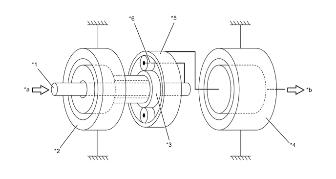
*1 Input Shaft *2 Motor Generator No. 1 (MG1) *3 Front Planetary Sun Gear *4 Motor Generator No. 2 (MG2) *5 Front Planetary Ring Gear *6 Front Planetary Carrier *a Engine Output *b To Multi Stage Shift Device
-
-
OPERATION
-
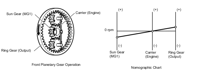
The nomographic chart below gives a visual representation of the planetary gear's rotational direction, rotational speed and torque balance. In the nomographic chart, the rpm of the 3 gears in the front planetary gear maintain a relationship in which they are invariably joined by a direct line.
-
Start-off
-
When starting off in a normal way, the vehicle is driven by the motive force of MG2. At this time, the rotational speed of the carrier is 0 rpm because the engine stops. Torque does not act on the sun gear because MG1 does not generate any torque. The sun gear rotates freely in the (-) direction due to the relationship with the rotation of the ring gear.
Condition of Front Planetary Gear Condition Sun Gear (MG1) Carrier (Engine) Ring Gear (Output) Rotational Direction - 0 + Torque 0 0 +
-
-
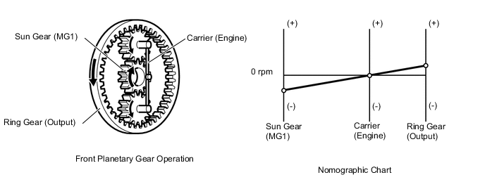
During Low Load and Constant-speed Cruising
-
The condition described below is one of the examples of the front planetary gear operation in low load and constant-speed cruising. The sun gear, carrier and ring gear rotate in the (+) direction. Torque acts on the carrier in the (+) direction. As the reaction to that, torque acts on the sun gear and ring gear in the (-) direction. MG1 generates electricity as a result of the torque that acts on the sun gear in the (-) direction.
Condition of Front Planetary Gear Condition Sun Gear (MG1) Carrier (Engine) Ring Gear (Output) Rotational Direction + + + Torque - + +
-
-
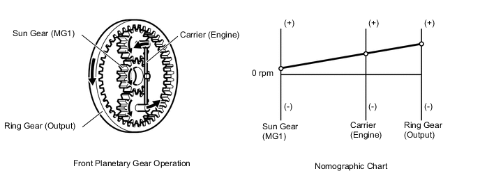
During Full Throttle Acceleration
-
When the large motive force of the engine is required, the engine speed becomes high. As a result, the relationship between the rotational speeds of the gears in the front planetary gear may become as in the nomographic chart below. The directions of torque that acts on each gear are the same as those in the low load and constant-speed cruising.
Condition of Front Planetary Gear Condition Sun Gear (MG1) Carrier (Engine) Ring Gear (Output) Rotational Direction + + + Torque - + +
-
-
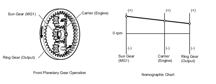
During Deceleration
-
During deceleration, the ring gear rotates by the rear wheels. At this time, the rotational speed of the carrier becomes 0 rpm because the engine stops. Torque does not act on the sun gear because MG1 does not generate any torque. The sun gear rotates freely in the (-) direction due to the relationship with the rotation of the ring gear.
Condition of Front Planetary Gear Condition Sun Gear (MG1) Carrier (Engine) Ring Gear (Output) Rotational Direction - 0 + Torque 0 0 -
-
-
Driving in Reverse
-
During reverse driving, the vehicle is driven mainly by the motive force of MG2. At this time, the rotational directions of the gears in the front planetary gear are reverse of those when starting in a normal way. The rotational speed of the carrier becomes 0 rpm because the engine stops. The sun gear rotates freely in the (+) direction due to the relationship with the rotation of the ring gear.
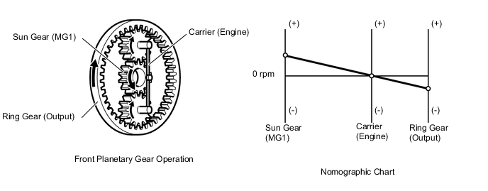
Condition of Front Planetary Gear Condition Sun Gear (MG1) Carrier (Engine) Ring Gear (Output) Rotational Direction + 0 - Torque 0 0 -
-
-
-