HYBRID TRANSMISSION SYSTEM
-
FUNCTION OF MAIN COMPONENTS
Component Function Hybrid Vehicle Transmission Assembly Motor Generator 1 (MG1) Driven by the engine and generates high-voltage electricity in order to operate MG2 and/or to charge the HV battery assembly. Also, MG1 functions as a starter to start the engine. Motor Generator 2 (MG2) Driven by electrical power from MG1 and/or the HV battery assembly, and generates motive force for the rear wheels. Also, MG2 generates electricity to recharge the HV battery assembly (regenerative braking) during braking or when the accelerator pedal is not depressed. Resolver (for MG1) Sends information about the rotational speed and direction of the MG1 to the MG ECU. Resolver (for MG2) Sends information about the rotational speed and direction of the MG2 to the MG ECU. Temperature Sensor (for MG1) Detects the temperature of the MG1. Temperature Sensor (for MG2) Detects the temperature of the MG2. Power Split Mechanism Splits the engine motive force between MG1 and the rear wheels. Multi Stage Shift Device Shifts the motive force output from the power split mechanism in 4 steps. Transmission Revolution Sensor Detects the output speed of the transmission. Mechanical Oil Pump Driven by engine power, supplies oil pressure to the valve body, lubricates the planetary gears and cools the motor generators. Transmission Valve Body Assembly Solenoid Valve SL1 Controls No. 1 clutch (C1) pressure. Solenoid Valve SL2 Controls No. 2 clutch (C2) pressure. Solenoid Valve SL3 Controls No. 1 brake (B1) pressure. Solenoid Valve SL4 Controls No. 2 brake (B2) pressure. Solenoid Valve SLT Controls line pressure. Solenoid Valve SC1 Uses a clutch control valve to switch the hydraulic pressure supplied to each solenoid valve (SL2 and SL3) on and off. Solenoid Valve SC2 Uses a clutch control valve to switch the hydraulic pressure supplied to each solenoid valve (SL2 and SL3) on and off. ATF Temperature Sensor Detects the ATF temperature. Oil Pump Motor Controller Drives the oil pump with motor assembly in accordance with a signal from the hybrid vehicle control ECU assembly to variably regulate the ATF discharge amount. Oil Pump with Motor Assembly
-
Supplies hydraulic pressure to the valve body, lubricates the planetary gears and cools the motor generators mainly when the engine is stopped. Also, it may supply hydraulic pressure to assist the mechanical oil pump.
-
Detects the motor coil temperature using the built-in oil pump motor thermistor.
Oil Pump Motor Relay Controlled by the hybrid vehicle control ECU assembly to supply power to the oil pump motor controller. Inverter with Converter Assembly Inverter Converts high-voltage DC (HV battery) into AC (MG1 and MG2) and vice versa (converts AC into DC). Boost Converter Boosts the voltage of the HV battery from DC 310.8 V to a maximum of DC 650 V and vice versa (drops from DC 650 V to DC 310.8 V). Motor Generator ECU (MG ECU) Controls the inverter and boost converter in accordance with signals received from the hybrid vehicle control ECU assembly, operating MG1 or MG2 as either a generator or motor. HV Battery Assembly Battery ECU Assembly Sends the HV battery assembly conditions signal (voltage, temperature and current) to the hybrid vehicle control ECU assembly. Yawrate Sensor Detects the angular velocity and lateral and longitudinal acceleration of the vehicle. Accelerator Pedal Sensor Assembly Converts the accelerator pedal position into an electrical signal and outputs the signal to the hybrid vehicle control ECU assembly. Stop Light Switch Assembly Detects the depressing of the brake pedal. Paddle Shift Switch (Transmission Shift Switch Assembly) Detects the driver's shift-up and shift-down operations. Drive Mode Select (Satellite Switch Set) Selects the drive mode. SNOW Mode Switch (Satellite Switch Set)* Selects the SNOW mode. EV Mode Switch (Integration Control and Panel Assembly) Selects EV mode, which drives using only the MG2 motive force. Hybrid Vehicle Control ECU Assembly
-
Performs comprehensive control of the hybrid system. This includes the hybrid vehicle transmission and HV battery assembly.
-
Monitors conditions of the HV battery such as voltage, temperature and current.
-
Sends the oil pump with motor assembly control signal to the oil pump motor controller.
-
Sends the cooling fan control signal to the ECM.
-
Cooperatively controls regenerative braking with the skid control ECU assembly.
-
Controls SMRs to connect and shut off the high-voltage circuits between the HV battery assembly and the inverter with converter assembly.
Shift Control ECU
-
Performs shift control for each shift position based on signals from the shift lever position sensor, P position switch and various ECUs and sends control signals to the hybrid vehicle control ECU assembly.
-
Sends signals to inform the hybrid vehicle control ECU assembly that fail-safe mode is entered when a malfunction occurs in the electronic shift lever system.
ECM
-
Controls the engine in accordance with the target engine speed and required engine motive force received from the hybrid vehicle control ECU assembly.
-
Sends the cam position sensor signals and crank position sensor signals to the hybrid vehicle control ECU assembly.
-
Calculates the appropriate fan speed and sends signals to the cooling fan controller.
*: Except Models for G.C.C. Countries
-
-
SYSTEM CONTROL
-
Control Description
-
The hybrid vehicle control ECU assembly performs switching in 4-stages with the 4-stage shift mechanism based on signals from the sensors and ECUs to optimize the efficiency of the system. During stage switching, a high-precision hydraulic pressure control circuit is used to achieve optimal driveability.
-
These 4 stages are composed of "1st Stage: Start-off", "2nd Stage: Acceleration", "3rd Stage: City Cruising to High-speed Acceleration" and "4th Stage: High-speed Cruising". 10 speed automatic transmission simulated shift control, which controls the engine speed in these 4 stages using MG1 to achieve 10-step shifting behavior, is used. As a result, a linear and forceful acceleration feeling is achieved.
-
AI-SHIFT control, which predicts the driving preference of the driver using the Driver's Mind Index (DMI)* and selects the optimal shift range, is used.
Tech Tips
*: An index that is calculated based on the front/rear and left/right acceleration of the vehicle and used to compare the driving condition (direction).
-
M mode control is used, which makes it possible to drive in the shift range selected by the driver's paddle shift switch (transmission shift switch assembly) operations when the shift position is M.
-
D-range paddle active control is used, which makes paddle shift switch (transmission shift switch) operations possible when the shift position is D.
-
-
Multi Stage Shift Device Control
-
The hybrid vehicle control ECU assembly controls the solenoid valves (SL1, SL2, SL3, SL4, SC1 and SC2) to operate the friction engagement components of the multi stage shift device, switching the shift range.
Shift Position R N D 1st 2nd 3rd 4th Solenoid Valve SL1 On ○ On On On Off SL2 Off ○ Off Off On On SL3 Off ○ Off On Off On SL4 On ○ On Off Off Off SC1 On ○ On On On On SC2 On ○ Off Off Off Off Clutch No. 1 Clutch (C1) Operates ○ Operates Operates Operates Does Not Operate No. 2 Clutch (C2) Does Not Operate ○ Does Not Operate Does Not Operate Operates Operates Brake No. 1 Brake (B1) Does Not Operate ○ Does Not Operate Operates Does Not Operate Operates No. 2 Brake (B2) Operates ○ Operates Does Not Operate Does Not Operate Does Not Operate 1-way Clutch 1-way Clutch (F1) Does Not Operate ○ Operates Does Not Operate Does Not Operate Does Not Operate Tech Tips
○: When the shift position is N, the system selects the shift range according to the vehicle speed.
-
-
10 Speed Automatic Transmission Simulated Shift Control
-
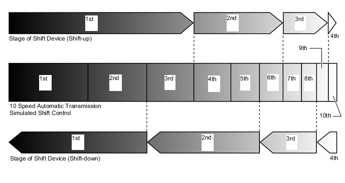
10 speed automatic transmission simulated shift control, which changes the engine speed using MG1 to achieve 10-step shifting behavior, is used. As a result, a linear and forceful acceleration feeling and a rhythmical shifting behavior are achieved.
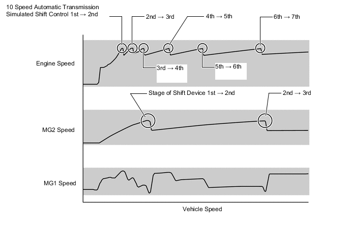
Figure 1. Distribution of Multi Stage Shift Device for 10 Speed Automatic Transmission Simulated Shift Control
-
-
Artificial Intelligence-shift Control (AI-shift Control)
-
This control selects the optimal shift range according to road conditions, such as uphill and downhill slopes, and accelerator pedal and brake pedal operations performed by the driver.
-
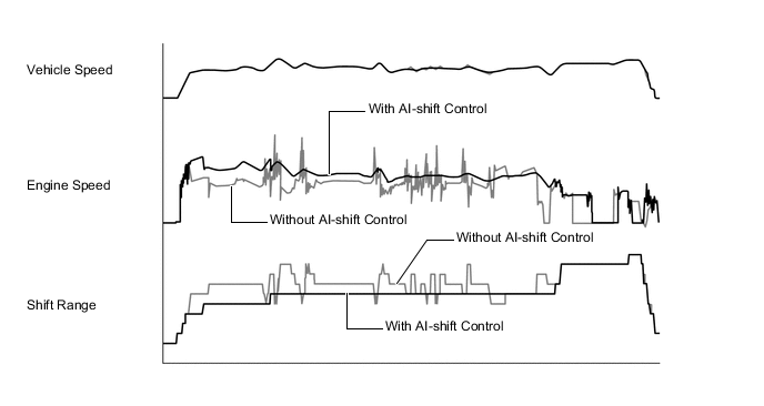
On uphill slopes, unnecessary upshifts are suppressed to constantly achieve the optimal amount of drive force. On downhill slopes, automatic downshifts are performed to ensure the optimal amount of deceleration force.
Figure 2. Uphill Slope Driving Data
-
The driving preference of the driver is predicted using the Driver's Mind Index (DMI), which is calculated from the front/rear and left/right acceleration, to perform optimal shift range selection that improves driveability.
-
AI-shift control is performed while driving when the shift position is D. When the shift position is M, AI-shift control is canceled. Also, when a paddle shift switch operation is performed while the shift position is D, AI-shift control is canceled and D-range paddle active control is given priority.
-
-
M Mode Control
-
When the shift position is M, the system switches from automatic shift mode to M mode control. M mode control makes it possible to select a shift speed position in 10 steps by performing paddle shift switch (transmission shift switch) operations. Also, during M mode control, the vehicle is driven with the shift speed position maintained.
-
M mode control is a control specification that makes it possible to enjoy sportier driving by using the engine high speed area effectively and switching the acceleration characteristics.
-
When accelerating with a shift speed position from M1 to M9 selected, the system automatically upshifts when the engine reaches the maximum speed in each range.
-
When the vehicle speed exceeds a certain speed while downshifting in response to a driver downshift request, shift range switching is restricted and the buzzer in the combination meter assembly sounds to warn the driver.
Restricted Speed when Downshifting Shift-down Operation Restricted Speed (Reference Value) 10th → 9th - 9th → 8th - 8th → 7th 201 km/h (124 mph) 7th → 6th 164 km/h (101 mph) 6th → 5th 134 km/h (83 mph) 5th → 4th 107 km/h (66 mph) 4th → 3rd 82 km/h (50 mph) 3rd → 2nd 68 km/h (42 mph) 2nd → 1st 51 km/h (31 mph)
-
-
D-range Paddle Active Control
-
When D-range paddle active control operates in response to a paddle shift switch (transmission shift switch) operation performed while the shift position is D, the system switches to range hold mode.
-
During D-range paddle active control, the system automatically shifts to a usable shift speed position within the selected shift range according to the driving condition.
-
The initial shift range when D-range paddle active control starts is determined according to the shift speed position before the paddle shift switch (transmission shift switch) operation was performed.
-
When the driver continues to drive the vehicle in range hold mode, the system automatically upshifts.
-
Automatic shifting will be reinstated under the following conditions:
-
The vehicle has stopped.
-
The driver continues to push the shift paddle switch (transmission shift switch assembly) in the "+" direction longer than 1 second.
-
The driver moves the shift lever to D.
-
The driver depresses the accelerator pedal for more than a predetermined amount of time.
-
-
-
-
FUNCTION
-
Gear Shift Indicator (Models with Gear Shift Indicator System)
-
Gear Shift Indicator is a system to promote upshifting to the fuel-efficient and optimal shift range in accordance with the driving conditions such as the accelerator pedal opening amount and the vehicle speed, etc. when the vehicle is being driven while the shift position is in M.
-
By driving in accordance with the upshifting recommendations indicated by the Gear Shift Indicator in the combination meter assembly, the driver can enhance environmental performance and improve fuel economy.
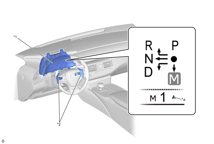
*1 Combination Meter Assembly *2 Paddle Shift Switch (Transmission Shift Switch Assembly) *a Gear Shift Indicator - -
-
-