FUEL SYSTEM
-
CONSTRUCTION
-
A high efficiency 1-plunger type fuel pump assembly (for high pressure) is used to reduce drive torque.
-
The fuel pump assembly (for high pressure) consists of the following parts:
-
A spill control valve which adjusts the discharged amount of high pressure fuel.
-
A plunger which is driven by the camshaft to pressurize the fuel.
-
A check valve which mechanically opens and closes the path to the fuel delivery pipe (for high pressure).
-
A relief valve which discharges fuel when the fuel pressure becomes too high in the high-pressure fuel system.
-
An orifice which reduces fuel pressure when the engine is stopped is used.
-
-
A roller lifter (fuel pump lifter assembly) is used to drive the plunger. As a result, high engine output and high fuel pressure are supported.
-
The fuel pump assembly (for high pressure) is installed to the camshaft bearing cap via the cylinder head cover sub-assembly and is driven by the cam installed to the exhaust camshaft (No. 2 camshaft).
-
A fuel pressure pulsation damper is installed inside the fuel pump assembly (for high pressure).
-
The high pressure fuel pressure is variably controlled between 2 and 20 MPa according to driving conditions to reduce friction losses.
-
A metal touch taper seal is used for the fuel pipe (for high pressure) fastener.
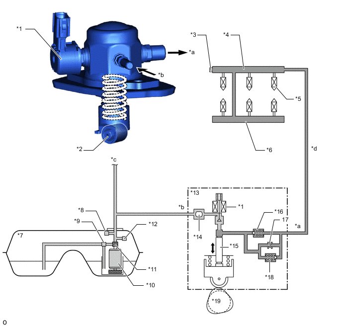
*1 Spill Control Valve *2 Roller Lifter (Fuel Pump Lifter Assembly) *3 Fuel Pressure Sensor (for High pressure) *4 Fuel Delivery Pipe with Sensor Assembly LH (for Direct Injection) *5 Fuel Injector Assembly (for Direct Injection) *6 Fuel Delivery Pipe RH *7 Fuel Tank Assembly *8 Fuel Main Valve Assembly *9 Jet Pump *10 Fuel Pump (for Low Pressure) *11 Fuel Pump Filter *12 Fuel Main Valve Assembly *13 Fuel Pump Assembly (for High Pressure) *14 Fuel Pressure Pulsation Damper *15 Plunger *16 Check Valve *17 Orifice *18 Relief Valve *19 Camshaft (Cam to Drive Fuel Pump Assembly (for High Pressure) - - *a High-pressure Fuel System (to Fuel Delivery Pipe (for Direct Injection)) *b Low-pressure Fuel System (from Fuel Tank Assembly) *c To Fuel Delivery Pipe (for Port Injection) *d Pipe of High-pressure Fuel System
-
-
OPERATION
-
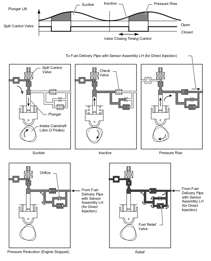
The plunger moves vertically to pressurize the fuel. The fuel is controlled to the necessary fuel pressure by closing the spill control valve, which is installed on the suction side of the fuel pump assembly (for high pressure), at the optimal timing during the compression stroke. When the spill control valve closes early, the effective stroke of the plunger becomes longer, increasing the fuel pressure.
-
The fuel, which is pressurized by the plunger and controlled to between 2 and 20 MPa, pushes open the check valve and is pressure-fed to the fuel delivery pipe with sensor assembly LH (for direct injection).
-
The fuel pressure is detected by the fuel pressure sensor installed in the fuel delivery pipe with sensor assembly LH (for direct injection) and feedback control is performed by the ECM to control the fuel pressure to the target value.
-
The fuel pressure is reduced by the orifice when the engine is stopped, thus improving fuel pressure control performance.
-
When the fuel pressure becomes too high in the high-pressure fuel system, the relief valve opens to discharge fuel and suppress the fuel pressure to or below the rated working pressure of the system.
-