HYBRID CONTROL SYSTEM
-
CONSTRUCTION
-
A cooling system for the inverter with converter assembly is provided to cool the inverter with converter assembly.
-
This cooling system activates when the power switch (push start switch) is turned to on (READY).
-
The inverter radiator and engine radiator are separate parts. The inverter radiator is mounted in front of the engine radiator.
-
The cooling fan is also shared by the engine radiator and A/C condenser.
Figure 1. LHD Models
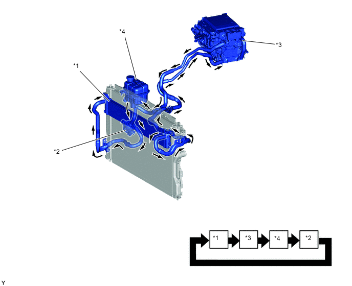
*1 Radiator Assembly *2 Inverter Water Pump with Motor Assembly *3 Inverter with Converter Assembly
-
Motor Generator ECU (MG ECU)
-
Boost Converter
-
Inverter
-
Hybrid Vehicle Converter Assembly (DC-DC Converter)
*4 Inverter Reservoir Tank Assembly 
Inverter Coolant Flow - - Figure 2. RHD Models
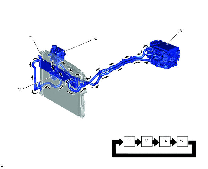
*1 Radiator Assembly *2 Inverter Water Pump with Motor Assembly *3 Inverter with Converter Assembly
-
Motor Generator ECU (MG ECU)
-
Boost Converter
-
Inverter
-
Hybrid Vehicle Converter Assembly (DC-DC Converter)
*4 Inverter Reservoir Tank Assembly Inverter Coolant Flow - - -
-