HYBRID CONTROL SYSTEM
-
FUNCTION OF MAIN COMPONENTS
Component Function 8GR-FXS Engine The 8GR-FXS engine is a high-expansion ratio Atkinson cycle engine which is compatible with the hybrid system and which generates drive force for driving and energy for electricity generation. L310*1 / L310F*2 Hybrid Transmission (Hybrid Vehicle Transmission Assembly) Motor Generator No. 1 (MG1)
-
Driven by the engine and generates high-voltage electricity in order to operate MG2 and/or to charge the HV battery . Also, MG1 functions as a starter to start the engine.
-
Operated to allow the gear ratio of the power split device unit to optimally suit the driving conditions of the vehicle.
Motor Generator No. 2 (MG2)
-
Driven by electrical power from MG1 and/or the HV battery and generates motive force for the rear wheels.
-
Generates electricity to recharge the HV battery (regenerative braking) during braking or when the accelerator pedal is not depressed.
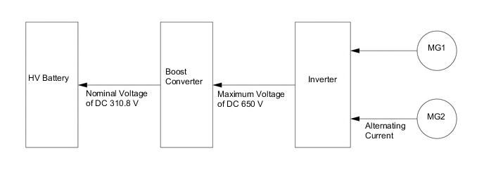
Power Split Device Splits the engine output into the motive force that operates the tires and the motive force that operates MG1 to generate electricity. Multi Stage Shift Device Shifts the output rotation of the power split device in 4 steps. Inverter with Converter Assembly Motor Generator ECU (MG ECU) Controls the boost converter and inverter in accordance with signals received from the hybrid vehicle control ECU assembly, operating MG1 or MG2 as either a generator or motor. Boost Converter Boosts the voltage of the HV battery from DC 310.8 V to a maximum of DC 650 V and vice versa (reduces from DC 650 V to DC 310.8 V). Inverter Converts high-voltage DC (HV battery ) into AC (MG1 and MG2) and vice versa (converts AC into DC). Hybrid Vehicle Converter Assembly (DC-DC Converter) Reduces the HV battery voltage from DC 310.8 V to approximately DC 14 V in order to supply electricity to body electrical components, as well as to recharge the auxiliary battery. HV battery
-
Supplies electrical power to MG1, MG2 and compressor with motor assembly in accordance with the driving conditions of the vehicle.
-
Charged by MG1 and MG2 in accordance with the State Of Charge (SOC) of the HV battery and the driving conditions of the vehicle.
-
Has a nominal (approximate) voltage of DC 310.8 V (actual voltage will vary depending on various conditions such as temperature, charge or discharge).
Service Plug Grip Shuts off the high-voltage circuit of the HV battery when this plug is removed for vehicle inspection or maintenance. Battery ECU Assembly
-
Monitors the conditions of the HV battery such as voltage, current and temperature, and transmits this information to the hybrid vehicle control ECU assembly.
-
Controls the battery cooling blower assemblies.
Battery Voltage Sensor Connected to the battery ECU assembly via a communication wire and sends information required for calculations performed by the hybrid vehicle control ECU assembly. Hybrid Battery Junction Block Assembly System Main Relays (SMRs) Connect and disconnect the high-voltage circuit between the HV battery and the inverter with converter assembly. The hybrid vehicle control ECU assembly controls the SMRs by turning them on or off as appropriate. HV Battery Current Sensor Measures the current of the HV battery . HV battery Temperature Sensors Detect temperatures in the parts of the HV battery and the intake air temperature from the battery cooling blower assembly. Battery Cooling Blower Assembly Operate under the control of the battery ECU assembly in order to cool the HV battery . Auxiliary Battery When the power switch (push start switch) is on (ACC) or on (IG), the auxiliary battery supplies power to the electrical equipment and ECUs. Battery State Sensor Assembly Calculates the current, voltage, temperature, SOC (battery charging percentage) and SOH (battery degradation percentage) of the auxiliary battery. Radiator Assembly Cools the inverter coolant. Inverter Water Pump with Motor Assembly Controlled in 5 stages by the hybrid vehicle control ECU assembly in accordance with inverter coolant temperatures in order to cool the inverter coolant. Interlock Switches
-
Inverter Terminal Cover
-
Connector Cover Assembly
-
Inverter Hybrid Connector Assembly
-
Service Plug Grip
Verify that the inverter terminal cover, connector cover assembly, inverter hybrid connector assembly and service plug grip are installed. Power Cable Connects the HV battery to the inverter with converter assembly, the inverter with converter assembly to MG1 and MG2, and the inverter with converter assembly to the compressor with motor assembly. Compressor with Motor Assembly Driven at a speed calculated by the air conditioning amplifier assembly, receives drive requests from the hybrid vehicle control ECU assembly and takes in, compresses and discharges refrigerant. Shift Lever Position Sensor Detects the shift lever position and outputs it to the shift control ECU. Steering Sensor Detects the direction and angle of the steering wheel. Accelerator Pedal Sensor Assembly Converts the accelerator pedal position into an electrical signal and outputs the signal to the hybrid vehicle control ECU assembly. Brake Pedal Stroke Sensor Assembly Directly detects the extent of the brake pedal stroke operated by the driver. Stop Light Switch Assembly Detects the brake pedal depressing signal. EV Mode Switch (Integration Control and Panel Assembly) Outputs the EV mode switch signal to the hybrid vehicle control ECU assembly when operated by the driver. Drive Mode Select (Satellite Switch Set)
-
Switches the drive mode between the following 6 modes.
-
Normal mode
-
Comfort mode
-
Eco mode
-
Sport S mode
-
Sport S+ mode
-
Custom mode
-
Outputs the Normal mode, Custom mode, Sport mode or Sport+ mode signal to the hybrid vehicle control ECU assembly and the ECM when operated by the driver.
-
Outputs the Eco mode or Comfort mode signal to the air conditioning amplifier assembly when operated by the driver.
Snow Switch (Satellite Switch Set)*3 Switches to Snow mode. Paddle Shift Switch (Transmission Shift Switch Assembly) Detects the driver's shift-up and shift-down operations. Steering Pad Switch Assembly (for Cruise Control) Turns the cruise control system and dynamic radar cruise control system on and off, and conducts various operations including vehicle speed setting, acceleration, deceleration and control cancellation. Hybrid Vehicle Control ECU Assembly
-
Performs comprehensive control of the hybrid system. This includes the electric continuously variable transmission and HV battery .
-
Receives information from various sensors as well as from ECUs (ECM, battery ECU assembly, MG ECU and skid control ECU), calculates the required torque and output power based on the information and sends the calculated result to the ECM, MG ECU and skid control ECU.
-
Monitors the SOC of the HV battery .
-
Controls the hybrid vehicle converter assembly (DC-DC converter).
-
Controls the inverter water pump with motor assembly.
ECM
-
Controls the engine in accordance with the target engine speed and required engine motive force received from the hybrid vehicle control ECU assembly.
-
Transmits the operating condition signals of the engine to the hybrid vehicle control ECU assembly.
Skid Control ECU Assembly
-
Calculates the regenerative braking force that is required and transmits the force to the hybrid vehicle control ECU assembly during braking.
-
Calculates the motive force that is required during the operation of TRC or VSC and transmits the force to the hybrid vehicle control ECU assembly.
Air Conditioning Amplifier Assembly Transmits various air conditioning state signals to the hybrid vehicle control ECU assembly. Airbag ECU Assembly Transmits the airbag deployment signal to the hybrid vehicle control ECU assembly and MG-ECU during a collision. Yawrate Sensor
-
Detects the vehicle's yaw rate.
-
Detects the vehicle's longitudinal and lateral acceleration.
Shift Control ECU Switches the shift position to P according to signals from the P position switch, and outputs R, N, D and M position switching requests to the hybrid vehicle control ECU assembly according to signals from the shift lever position sensor. Combination Meter Assembly Hybrid System Indicator Indicates the hybrid system output and charging conditions of the HV battery to inform the driver. READY Indicator Light Informs the driver that the vehicle is ready to be driven. EV Drive Indicator Light Informs the driver that the EV drive is entered. MIL Turns on when there is a malfunction in the engine control system. Master Warning Light Illuminates or flashes according to warning messages displayed on the multi-information display. Shift Position Indicator Displays the shift position. EV Mode Indicator Light Displays the EV mode. Snow Mode Indicator Light* Displays the Snow mode. Drive Mode Indicator Light Displays the drive mode. Multi-information Display
-
Displays the hybrid system output condition according to the energy flow.
-
Displays a warning message when EV mode is rejected or canceled.
-
Displays a warning message corresponding to each system malfunction.
*1: 2WD Models
*2: AWD Models
*3: Models with Snow mode
-
-
OPERATING CONDITION
-
Hybrid System Activation (On (READY) State)
-
The hybrid system can be activated by pressing the power switch (push start switch) while the brake pedal is being depressed. At this time, the READY indicator light flashes until the system check is completed. When the READY indicator light turns on, the hybrid system has started and the vehicle is ready to be driven.
-
Even if the driver turns the power switch (push start switch) on (READY), sometimes the hybrid vehicle control ECU assembly will not start the engine. The engine will only start if conditions such as engine coolant temperature, SOC, HV battery temperature and electrical load require an engine start.
-
After driving, when the driver stops the vehicle and the shift position is P, the hybrid vehicle control ECU assembly allows the engine to continue running. The engine will stop after the SOC, HV battery temperature and electrical load reach a specified level.
Note
When the hybrid system is unavoidably required to be stopped while driving, the system can be forced to stop by pressing and holding the power switch (push start switch) for approximately 2 seconds or more or by pushing the power switch (push start switch) 3 times or more in a row. At this time, the power source mode will turn on (ACC).
-
-
EV Mode
-
When the following conditions in the table below are satisfied, the EV mode is entered by using the EV mode switch.
Condition
-
The hybrid system temperature is not high. The hybrid system temperature will be high when the outside air temperature is high or after the vehicle has traveled uphill or at high speeds.
-
The hybrid system temperature is not low. The hybrid system temperature will be low after the vehicle has been left for a long time when the outside air temperature is low.
-
The State Of Charge (SOC) of the HV battery is approximately 50% or more.
-
The vehicle speed is approximately 55 km/h (34 mph) or less (engine coolant temperature is 70°C (158°F) or more). *1
-
The vehicle speed is approximately 55 km/h (34 mph) or less (engine coolant temperature is 40°C (104°F) or more). *2
-
The accelerator pedal depression amount is at a certain level or below.
-
The defroster is off.
-
The cruise control system is not operating.
-
The shift position is not "M".
*1: Models for Korea
*2: Except models for Korea
Tech Tips
If the EV mode switch is operated during the period between the power switch (push start switch) being turned to on (IG) and the engine starting (approximately 10 seconds), the EV mode display will be shown first.
-
-
If any condition is not satisfied and the EV mode switch is selected, a message is displayed on the multi-information display to inform the driver that the attempt to enter EV mode is rejected, and the EV mode cannot be entered.
-
When EV mode has been automatically canceled, a message is displayed to indicate that EV mode has been canceled.
-
-
Eco Mode
-
Eco mode is entered by using the drive mode select.
-
The Eco mode setting is recorded by the hybrid vehicle control ECU assembly. This setting will not be reset when the power switch (push start switch) is turned off.
-
Eco mode will be canceled when the drive mode select is switched to any mode other than Eco mode.
-
-
Inspection Mode
-
Inspection mode is entered by using the TechStream (GTS) or the accelerator pedal. For details, refer to the Repair Manual.
-
-
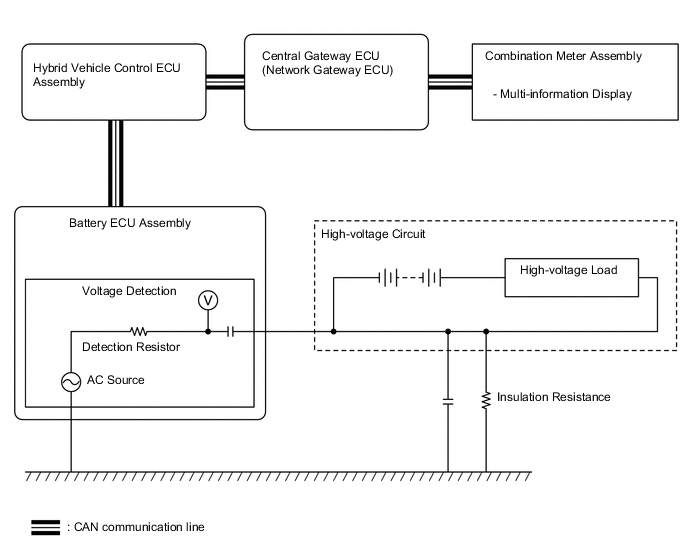
Detection of Insulation Resistance Decrease
-
A leak detection circuit is built into the battery ECU assembly. The leak detection circuit constantly monitors that the insulation resistance between high-voltage circuits and body ground is maintained.
-
If the insulation resistance decreases below a specified level, a Diagnostic Trouble Code (DTC) is stored, and the driver is informed of the abnormality condition by the multi-information display.
-
The leak detection circuit has an AC source and causes a small amount of AC to flow to the high-voltage circuit (positive and negative).
-
AC flows as shown in the following illustration. AC flows via a detection resistor, a capacitor and body ground.
-
The more vehicle insulation resistance decreases, the more voltage reduces at the detection resistor and the lower the amplitude of the AC waves. The insulation resistance value (tester data name: short wave highest value) is detected based on the amplitude of AC waves.
-
-
-
SYSTEM CONTROL
Electronic Control of Hybrid System Control Outline Hybrid Vehicle Control
-
The hybrid vehicle control ECU assembly calculates the total output according to driving conditions and outputs request signals to ECUs to control the motive force. The hybrid vehicle control ECU assembly calculates it according to the output requested by the driver, which is calculated from signals from various sensors and the shift control ECU (such as the accelerator opening angle and shift position switching requests), and the SOC value calculated from HV battery condition signals from the battery ECU assembly (HV battery voltage, current and temperature).
-
The hybrid vehicle control ECU assembly calculates the engine motive force based on the target motive force, which has been calculated based on the requirements of the driver and vehicle conditions. In order to create this motive force, the hybrid vehicle control ECU assembly transmits signals to the ECM.
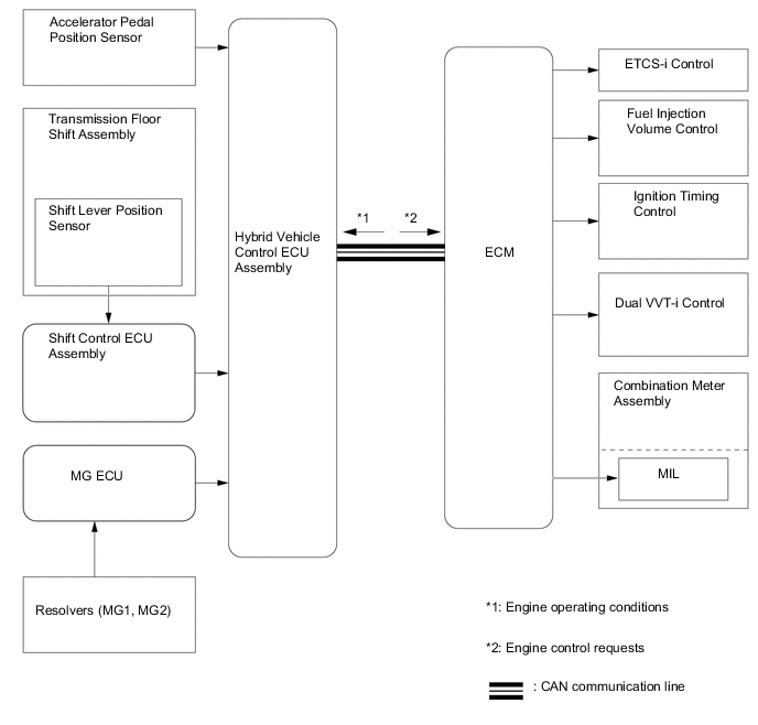
System Monitoring Control The hybrid vehicle control ECU assembly monitors the State Of Charge (SOC) of the HV battery and the temperature of the HV battery, MG1 and MG2, in order to optimally control these items. Shut Down Control When the shift position is in N, the hybrid vehicle control ECU assembly performs shut down control to stop driving MG1 and MG2. System Main Relay (SMR) Control To ensure that it is possible to connect and disconnect the high voltage circuits reliably, the hybrid vehicle control ECU assembly controls the 3 SMRs to connect and disconnect the high voltage circuits from the HV battery. The hybrid vehicle control ECU assembly also uses the timing of the operation of the SMRs to monitor the operation of the relay contacts. State Of Charge (SOC) Control The hybrid vehicle control ECU assembly constantly performs charge/discharge control based on the calculated SOC in order to maintain the SOC within its target range. Inverter Coolant Cooling Control In order to cool the inverter with converter assembly the hybrid vehicle control ECU assembly regulates the inverter water pump with motor assembly in accordance with the signals from the temperature sensor for the inverter coolant. ECM Control The ECM receives the target engine speed and required engine motive force sent from the hybrid vehicle control ECU assembly, and controls the Electronic Throttle Control System-intelligent (ETCS-i), fuel injection volume, ignition timing, Dual Variable Valve Timing-intelligent (Dual VVT-i). Motor Generator Main Control
-
MG1, which is driven by the engine, generates high voltage (alternating current) in order to operate MG2, and charge the HV battery via the inverter. Also, MG1 functions as a starter to start the engine.
-
MG2, which is driven by electrical power from MG1 and/or the HV battery, generates motive force for the front wheels.
-
MG2 generates electricity to charge the HV battery (regenerative braking control) during braking or when the accelerator pedal is not being depressed.
-
Rotation sensors detect the speed and the position of MG1 and MG2 for use by the hybrid vehicle control ECU assembly. Rotation sensor signals are transmitted to the hybrid vehicle control ECU assembly via the MG ECU.
-
Temperature sensors mounted in MG1 and MG2 detect the temperature for use by the hybrid vehicle control ECU assembly.
Boost Converter Control
-
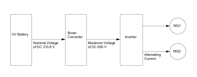
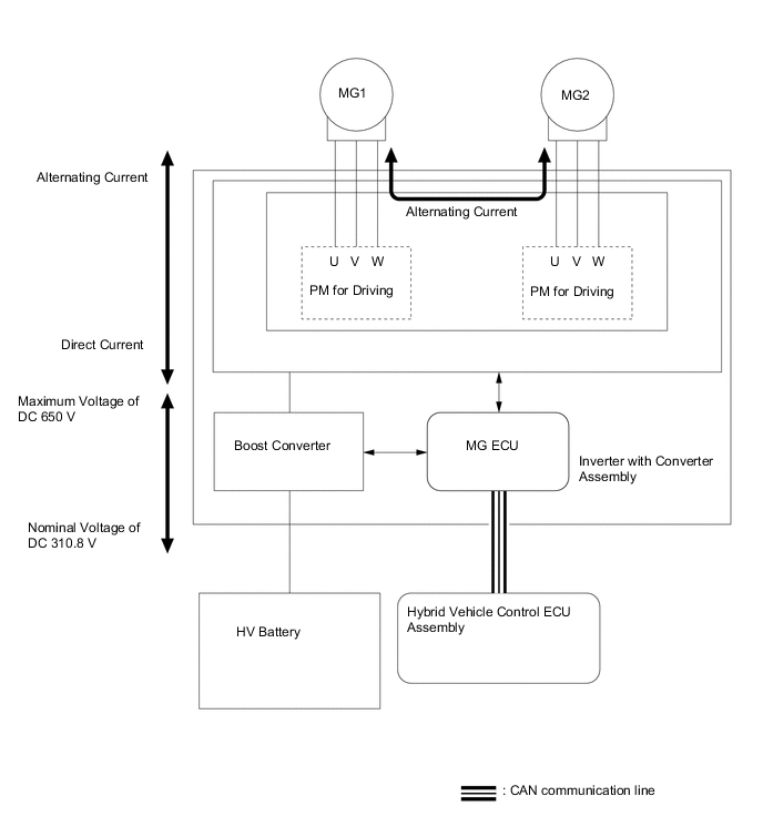
The boost converter boosts the HV battery voltage from a nominal voltage of DC 310.8 V to a maximum voltage of DC 650 V, in accordance with the signals provided by the hybrid vehicle control ECU assembly via the MG ECU.
-
The inverter converts the alternating current generated by MG1 or MG2 into a direct current. The boost converter reduces the generated voltage from up to 650 V to approximately DC 310.8 V for the HV battery in accordance with the signals provided by the hybrid vehicle control ECU assembly via the MG ECU.
Inverter Control
-
The inverter converts direct current from the HV battery into an alternating current for MG1 and MG2, or vice versa, in accordance with the signals provided by the hybrid vehicle control ECU assembly via the MG ECU. In addition, the inverter is used to transfer power from MG1 to MG2.
-
Via the MG ECU, the hybrid vehicle control ECU assembly sends signals to the power transistors on the Power Modules (PMs) in the inverter for switching the U, V and W phases of MG1 and MG2, in order to drive MG1 and MG2.
-
The hybrid vehicle control ECU assembly shuts down the inverter when the ECU receives an overheat, overcurrent or fault voltage signal from the inverter via the MG ECU.
Hybrid Vehicle Converter Assembly Control
-
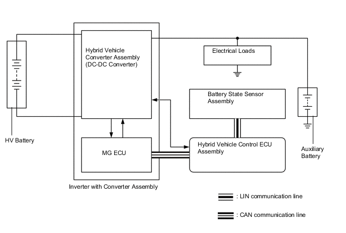
Hybrid vehicle converter assembly control reduces the voltage from DC 310.8 V (nominal) to DC 14 V (nominal) in order to supply electricity to body electrical components, as well as to recharge the auxiliary battery (DC 12 V).
-
This converter keeps the auxiliary battery at a constant voltage.
Battery ECU Control
-
The battery ECU assembly calculates the SOC from HV battery condition signals (voltage, current and temperature) and sends the result to the hybrid vehicle control ECU assembly.
-
The battery ECU assembly sends the operation signal to battery cooling blower assembly and detects the blower speed feedback frequency which is necessary to perform the cooling system control.
-
A leakage detection circuit is provided in the battery ECU assembly in order to detect any electrical leakage from the HV battery or high-voltage circuit.
Shift Control The hybrid vehicle control ECU assembly detects the shift position (P, R, N, D or M) in accordance with the signals sent by the shift control ECU and the paddle shift switch (transmission shift switch assembly), and controls MG1 and MG2 and the engine to match the selected shift position. Skid Control ECU Control Regenerative Braking Cooperative Control During braking, the skid control ECU calculates the required regenerative braking force and transmits a signal to the hybrid vehicle control ECU assembly. Upon receiving this signal, the hybrid vehicle control ECU assembly transmits an actual regenerative braking control value to the skid control ECU. Based on this result, the skid control ECU calculates and executes the required hydraulic pressure braking force. TRC/VSC Cooperative Control The skid control ECU transmits a request to the hybrid vehicle control ECU assembly to limit motive force while the TRC or VSC is operating. The hybrid vehicle control ECU assembly controls the engine, MG1 and MG2 in accordance with the present driving conditions in order to suppress the motive force. During Collision Control During a collision, if the hybrid vehicle control ECU assembly receives an airbag deployment signal from the airbag ECU assembly, the ECU turns the SMRs off in order to shut off the high voltage power supplied to the hybrid system by the HV battery . Dynamic Radar Cruise Control System Operation Control Upon receiving acceleration and deceleration request signal from the driving support ECU assembly, the hybrid vehicle control ECU assembly optimizes the motive forces of the engine and MG2 in order to obtain the target vehicle speed. EV Mode Control When the EV mode switch is manually operated by the driver, the hybrid vehicle control ECU assembly operates to run the vehicle using only MG2 if the required conditions are satisfied. Drive Mode Select Control Drive mode select control optimally controls the outputs of MG1, MG2 and the engine in accordance with the following drive modes: Normal, Comfort, Eco, Sport S, Sport S+ and Custom modes. Snow Mode Control*1 When the Snow mode switch is manually operated by the driver, the hybrid vehicle control ECU assembly controls motive force for the acceleration operation, achieving smooth start-off on slippery roads such as snowy roads. Indicator and Warning Light Control Indicator and warning light control illuminates and blinks the warning lights, or shows messages on the multi-information display to inform the driver of the vehicle conditions or system malfunctions. Brake Override System The driving torque is restricted when both the accelerator and brake pedals are depressed. (For the activation conditions and inspection method, refer to the Repair Manual.) Drive Start Control If an abnormal shift (R→D, D→R, N→R, P→D*, P→R*) is detected while accelerating, a warning is displayed in the combination meter assembly and driving force is reduced to limit the acceleration, helping to avoid a collision. *1: Models with Snow mode
*2: Depending on the situation, the shift position cannot be changed.
-
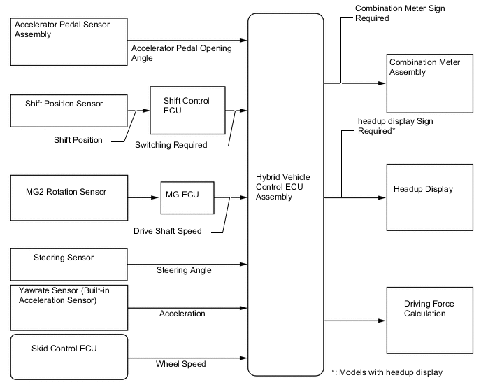
Hybrid Vehicle Control
-
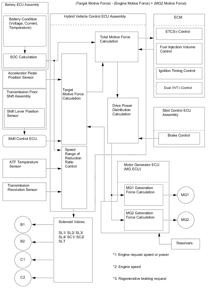
The hybrid vehicle control ECU assembly detects the amount of accelerator pedal depression using the signals from the accelerator pedal position sensor. The hybrid vehicle control ECU assembly receives vehicle speed signals from the MG2 rotation sensor and detects the shift position signal from the shift position sensor. The hybrid vehicle control ECU assembly determines the vehicle operating conditions in accordance with this information, and optimally controls the motive forces of MG1, MG2 and engine. Furthermore, the hybrid vehicle control ECU assembly optimally controls the output and torque of MG1, MG2 and the engine in order to achieve lower fuel consumption and cleaner exhaust emissions.
-
The hybrid vehicle control ECU assembly calculates the engine motive force based on the calculated target motive force, and by taking the State Of Charge (SOC) of the HV battery and the temperature of the HV battery into consideration. The value obtained by subtracting the engine motive force from the target motive force is the MG2 motive force.
-
The ECM appropriately performs ETCS-i control, fuel injection volume control, ignition timing control, Dual VVT-i system control based on signals sent by the hybrid vehicle control ECU assembly in order to achieve the required engine motive force. Furthermore, the hybrid vehicle control ECU assembly appropriately operates the MG1 and MG2 in order to achieve the required MG2 motive force.
Figure 1. Flow of Motive Force Calculation
-
-
System Monitoring Control
-
The hybrid vehicle control ECU assembly constantly monitors the State Of Charge (SOC) of the HV battery . When the SOC is below the lower level, the hybrid vehicle control ECU assembly increases the power output of the engine to operate MG1, which charges the HV battery . When the engine is stopped, MG1 operates to start the engine. Then, the engine operates MG1 to charge the HV battery .
-
If the SOC is low, or the temperature of the HV battery , MG1 or MG2 is higher than a specified value, the hybrid vehicle control ECU assembly restricts the motive force applied to the drive wheels until the value of the abnormal item returns to normal.
-
-
Shut Down Control
-
Generally, MG1 and MG2 are shut down when the shift position is in N. In order to stop providing motive force, it is necessary to stop driving MG1 and MG2, because MG2 is mechanically joined to the rear wheels.
-
During driving, if the brake pedal is depressed and a wheel locks up, the ABS function is activated. Afterwards, low torque is requested from MG2 to provide supplemental power in order to restart the rotation of the wheel. Even if the shift position is in N at this time, the shut down function is canceled to allow the wheel to rotate. After the wheel rotation has been restarted, the system resumes its shut down function.
-
When the vehicle is driven with the shift position in D or M and the brake pedal is depressed, regenerative braking occurs. At this time, if the driver moves the shift position to N, the brake hydraulic pressure increases while the request torque of the regenerative braking decreases gradually so as not to create a sluggish brake feel. The system then performs the shut down function.
-
When the speed of MG1 and MG2 is above a specified threshold, the shut down function is canceled.
-
-
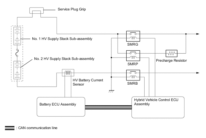
System Main Relay (SMR) Control
-
The SMRs are the relays that connect and disconnect the power source of the high-voltage circuit upon receiving a command from the hybrid vehicle control ECU assembly.
-
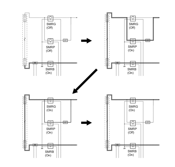
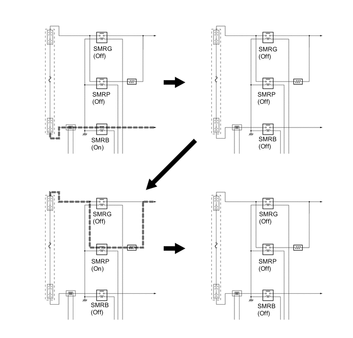
The hybrid vehicle control ECU assembly turns the SMRB on, and then turns the SMRP on. After the hybrid vehicle control ECU assembly has turned the SMRG on, the ECU turns the SMRP off. As the controlled current is initially allowed to pass through a resistor in this manner, the contact point in the circuit is protected from damage that could be caused by a rush current.
-
First, the hybrid vehicle control ECU assembly turns the SMRG off. After the ECU has determined whether the contact points of the SMRG are stuck, it turns the SMRB off. Subsequently, the hybrid vehicle control ECU assembly turns the SMRP on in order to determine whether the contact points of the SMRB are stuck. Then, the ECU turns the SMRP off.
-
If the hybrid vehicle control ECU assembly detects that the contact points are stuck, the ECU illuminates the master warning light and indicates "CHECK HYBRID SYSTEM" on the multi-information display, and stores a Diagnostic Trouble Code (DTC) in memory.
-
-
State Of Charge (SOC) Control
-
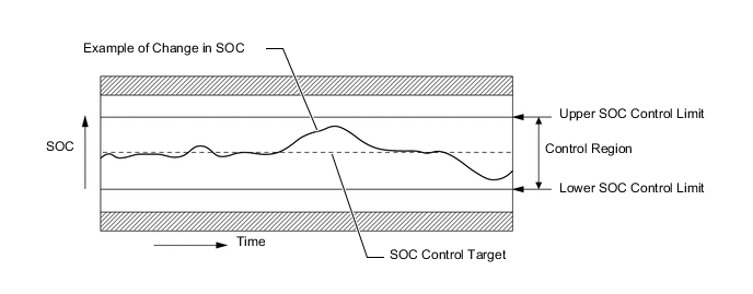
The hybrid vehicle control ECU assembly calculates the SOC of the HV battery by estimating its charging and discharging amperages, in order to control the SOC. This allows the hybrid system to make control decisions based on the power stored in the battery.
-
While the vehicle is in motion, the HV battery undergoes repetitive charge/discharge cycles, as the battery becomes discharged by MG2 during acceleration and charged by regenerative braking during deceleration. The hybrid vehicle control ECU assembly calculates the SOC based on the amount of HV battery charge/discharge detected by the current sensor. The hybrid vehicle control ECU assembly constantly performs charge/discharge control based on the calculated SOC value in order to maintain the SOC within its target range.
-
-
Inverter Coolant Cooling Control
-
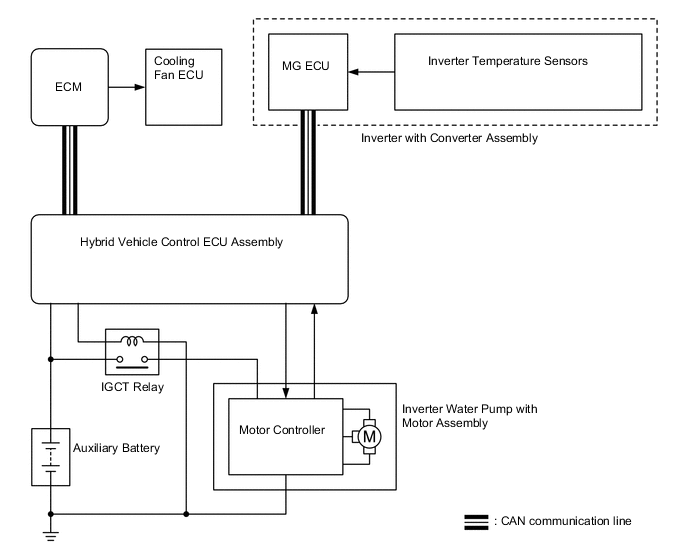
The hybrid vehicle control ECU assembly receives the signal from the temperature sensor for the inverter coolant. Then, the hybrid vehicle control ECU assembly actuates the inverter water pump with motor assembly in 5 levels using duty cycle control, in order to cool the inverter coolant.
-
When the inverter coolant temperature rises above a certain level, the hybrid vehicle control ECU assembly transmits a radiator fan drive request signal to the cooling fan ECU via the ECM. In response to the signal, the cooling fan ECU actuates the radiator fan to restrain the increases in the inverter coolant temperature, ensuring the cooling of the inverter with converter assembly.
-
The MG ECU converts the temperature sensor signal into a digital signal, and transmits the signal to the hybrid vehicle control ECU assembly via CAN communication.
-
-
HV battery Cooling Control
-
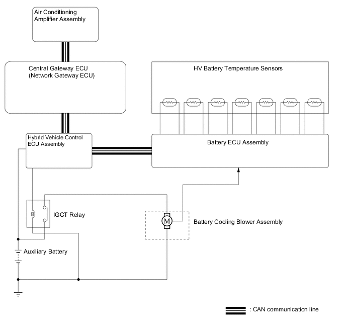
The battery ECU assembly detects increases in battery temperature via the 7 temperature sensors in the HV battery . Then, the battery ECU assembly steplessly actuates the battery cooling blower assembly using duty cycle control, in order to maintain the temperature of the HV battery within the specified range.
-
If there is any leeway in the HV battery temperature while the air conditioning system is operating and cooling down the cabin, the hybrid vehicle control ECU assembly turns the battery cooling blower assembly off or sets them to a low speed. The purpose of this control is to give priority to cooling down the cabin. If this control is not performed, air being taken from the cabin for battery cooling slows the cooling of the cabin by the air conditioning system.
-
-
ECM Control
-
The ECM receives the target engine speed and required engine motive force which were sent from the hybrid vehicle control ECU assembly, and controls the ETCS-i system, fuel injection volume, ignition timing, Dual VVT-i system.
-
The ECM transmits information about the engine operating conditions to the hybrid vehicle control ECU assembly.
-
Upon receiving an engine stop signal from the hybrid vehicle control ECU assembly in accordance with basic hybrid vehicle control, the ECM will stop the engine.
-
When a malfunction occurs in the system, the ECM activates the MIL in accordance with requests from the hybrid vehicle control ECU assembly.
-
-
Motor Generator Main Control
-
MG1, which is driven by the engine, generates high voltage (alternating current) in order to power MG2 and charge the HV battery . Also, MG1 functions as a starter to start the engine.
-
MG2 is driven by electrical power from the HV battery and/or MG1, and it generates motive force for the rear wheels.
-
MG2 generates electricity to charge the HV battery during braking (regenerative braking control), or when the accelerator pedal is not being depressed.
-
MG1 and MG2 are shut down when the shift position is in N. In order to stop providing motive force, it is necessary to stop driving MG1 and MG2, because MG1 and MG2 are mechanically joined to the drive wheels.
-
The MG ECU, which follows the commands of the hybrid vehicle control ECU assembly, controls MG1 and MG2 via the Power Modules (PMs), for driving the vehicle. 6 Insulated Gate Bipolar Transistors (IGBTs) switch on and off to control each individual motor generator in accordance with operation as either a motor or a generator.
-
The illustration below describes the basic control when a motor generator functions as a motor.
-
The IGBTs switch on and off to supply 3-phase alternating current to the motor generator.
-
In order to create the motive force required of the motor generator as calculated by the hybrid vehicle control ECU assembly, the MG ECU switches the IGBTs on and off and controls the speed, in order to control the speed of the motor generator.
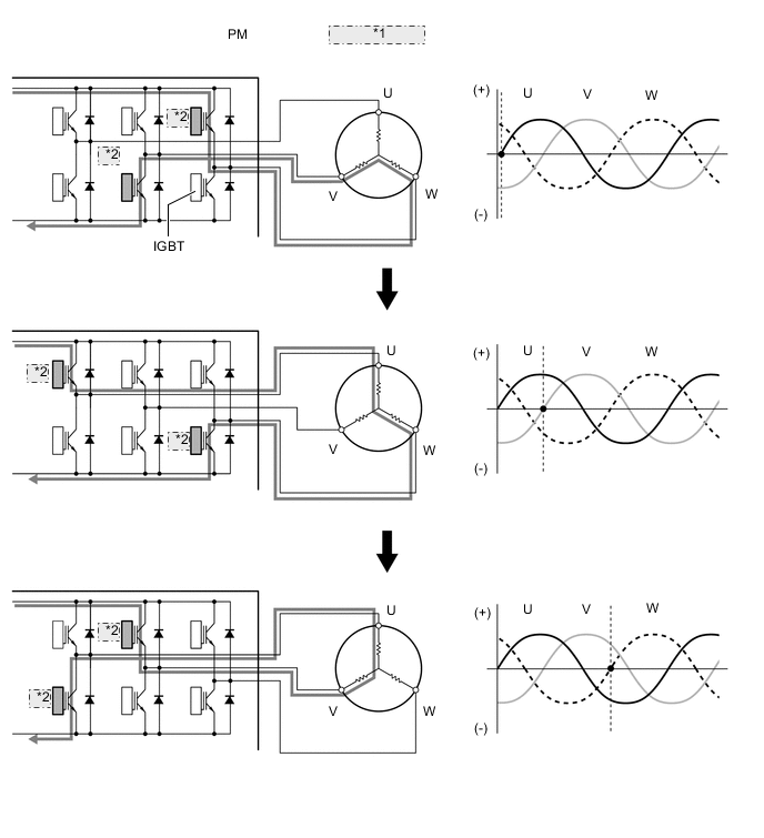
*1 Motor Generator *2 On
-
-
The illustration below describes the basic control used when a motor generator functions as a generator.
-
The current that is generated sequentially by the 3 phases of the motor generator, which is driven by the wheels, is utilized to charge the HV battery or drive another motor generator.
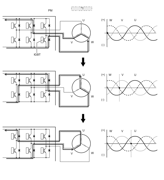
*1 Motor Generator
-
-
-
Boost Converter Control
-
The boost converter boosts the HV battery voltage of DC 310.8 V (nominal) up to a maximum voltage of DC 650 V, in accordance with the signals provided by the hybrid vehicle control ECU assembly via the MG ECU.
-
The inverter converts the alternating current generated by MG1 or MG2 into direct current. The boost converter drops the voltage of DC 650 V (maximum) to DC 310.8 V (nominal) for the HV battery in accordance with the signals provided by the hybrid vehicle control ECU assembly via the MG ECU.
-
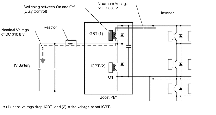
The boost converter consists of a reactor and a boost Power Module (PM) with built-in Insulated Gate Bipolar Transistors (IGBTs) that perform switching control.
-
The reactor is an electronic component that has characteristics that resist changes in current flow. If a circuit containing a reactor is switched on and then off, the reactor will attempt to maintain current flow after being switched off. At the time of voltage reduction, these characteristics also assist in smoothing the output from the voltage drop IGBT (1). The reactor can be charged quickly by turning on the boost IGBT (2).
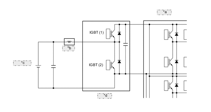
*a Inverter *b Reactor *c HV Battery *d Boost PM -
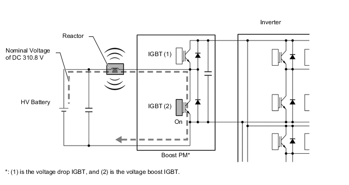
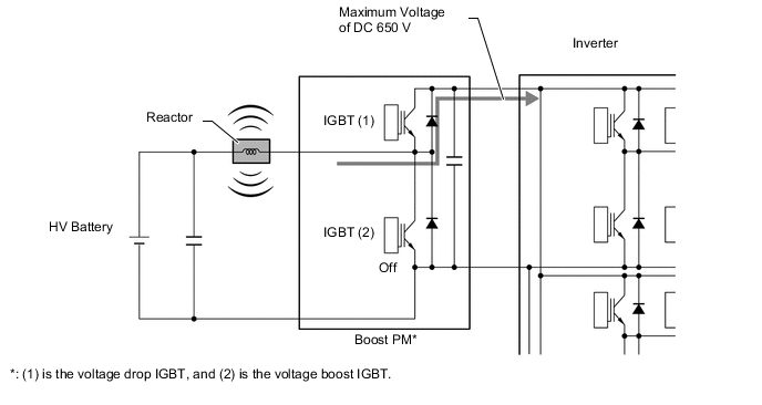
The boost converter boosts the HV battery voltage from DC 310.8 V (nominal) to a voltage of up to DC 650 V as described in the following 2 steps:
-
The IGBT (2) turns on, causing the electrical power of the HV battery (nominal voltage of DC 310.8 V) to charge the reactor. As a result, the reactor stores power.
-
The IGBT (2) turns off, causing the reactor to produce an electromotive force (the current continues to flow from the reactor). This electromotive force causes the voltage to rise to a maximum of DC 650 V.
-
-
The alternating current which is generated by MG1 or MG2 for the purpose of charging the HV battery is converted into direct current (maximum voltage approximately 650 V) by the inverter. Then, the boost converter is used to drop the voltage to approximately DC 310.8 V. This is accomplished by IGBT (1) being switched on and off using duty cycle control, intermittently interrupting the electrical power provided to the reactor by the inverter.
-
-
Inverter Control
-
The inverter converts the direct current from the HV battery into alternating current for MG1 and MG2, or vice versa, in accordance with the signals provided by the hybrid vehicle control ECU assembly via the MG ECU. In addition, the inverter takes power generated by MG1 and supplies it to MG2. However, the electricity generated by MG1 is converted into direct current inside the inverter before being converted back into alternating current by the inverter for use by MG2. This is necessary because the frequency of the alternating current output by MG1 is not appropriate for control of MG2.
-
The MG ECU transmits signals to the power transistors in the inverter for switching the U, V and W phases of stator coils of MG1 and MG2 based on the rotor position information sent by the MG1 and MG2 rotation sensors.
-
When the shift lever is in N, or the hybrid vehicle control ECU assembly has received an overheating, overcurrent, or fault voltage signal from the inverter, the hybrid vehicle control ECU assembly transmits a shut down control signal to the inverter, in order to turn off the power transistors to electrically disconnect MG1 and MG2.
-
-
Hybrid Vehicle Converter Assembly Control
-
The hybrid vehicle converter assembly (DC-DC converter) reduces the nominal voltage of the HV battery from DC 310.8 V to approximately DC 14 V in order to supply electricity to the electrical components, as well as to recharge the auxiliary battery.
-
In order to regulate the output voltage from the hybrid vehicle converter assembly (DC-DC converter), the hybrid vehicle control ECU assembly transmits the output voltage request signal to the hybrid vehicle converter assembly in response to the battery state sensor signals.
-
-
Battery ECU Assembly Control
-
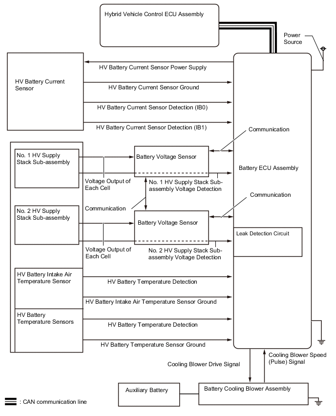
The battery ECU assembly converts the HV battery related signals (voltage, current and temperature) into digital signals, and transmits them to the hybrid vehicle control ECU assembly via CAN communication. These signals are needed to determine the charge or discharge values that are calculated by the hybrid vehicle control ECU assembly.
-
A leakage detection circuit is provided in the battery voltage sensor in order to detect any electrical leakage from the HV battery or high voltage circuit.
-
The battery voltage sensor is connected to the battery ECU assembly via a communication wire and sends information required for calculations performed by the hybrid vehicle control ECU assembly, such as the voltages of the No. 1 HV supply stack sub-assembly and No. 2 HV supply stack sub-assembly, to the battery ECU assembly.
-
-
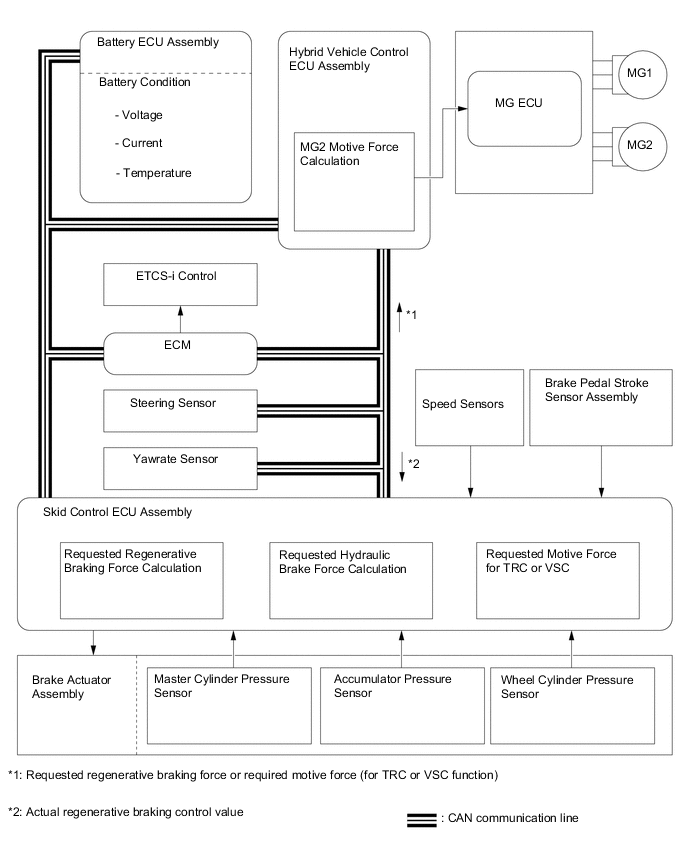
Skid Control ECU Control
-
The skid control ECU calculates the total brake force needed based on the master cylinder pressure in the brake actuator and brake pedal stroke sensor assembly signal generated when the driver depresses the brake pedal.
-
After calculating the total brake force required, the skid control ECU sends a regenerative braking force request to the hybrid vehicle control ECU assembly. The hybrid vehicle control ECU assembly replies with the amount of regenerative braking force that is possible.
-
The hybrid vehicle control ECU assembly uses MG2 to create minus torque (deceleration force), carrying out the regenerative braking.
-
The skid control ECU controls the brake actuator and generates wheel cylinder pressure. The pressure that is generated is what remains after the actual regenerative braking control value has been subtracted from the total required brake force.
-
The skid control ECU outputs a request to the hybrid vehicle control ECU assembly to limit motive force while the TRC or VSC is operating to control wheel spin. The hybrid vehicle control ECU assembly controls the engine, MG1 and MG2 in accordance with the present driving conditions in order to suppress the motive force.
-
-
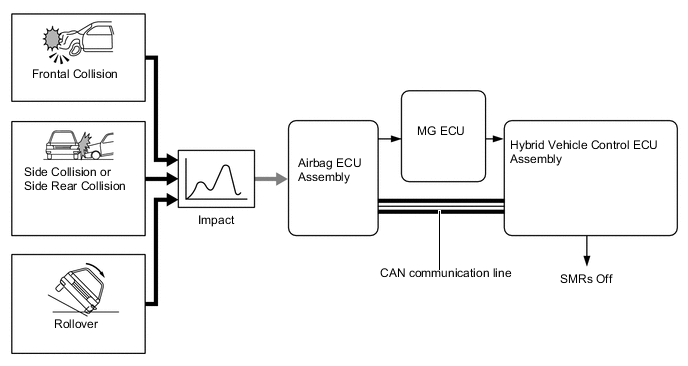
During Collision Control
-
If the vehicle encounters one of the situations described below, the hybrid vehicle control ECU assembly will shut down the power supply by turning the System Main Relays (SMRs) off, for safety.
-
The MG-ECU and hybrid vehicle control ECU assembly receives an airbag deployment signal from the airbag ECU assembly during a frontal collision, side collision, side rear collision or rollover. In the event of a rear collision, the airbag ECU assembly also sends a signal.
-
-
Drive Start Control
-
When abnormal driver accelerator pedal and shift operations are detected, the system restricts the driving force and informs the driver.
Tech Tips
-
When the VSC OFF switch is operated to turn the TRC off, the system does not operate.
-
When the system is operating, even if the driver depresses and holds the accelerator pedal, driving force may increase on an uphill slope and decrease on a downhill slope. This behavior allows the system to restrict the vehicle speed and acceleration below the predetermined limit on slopes and is not a malfunction.
-
-
Shift Change Control
-
Responds to shift operations with the accelerator pedal depressed.
-
Changes the limit amount according to the manual shift operation pattern.
-
Corrects driving force according to the road grade and steering angle.
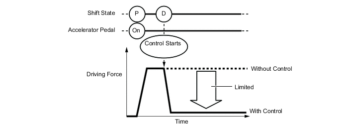
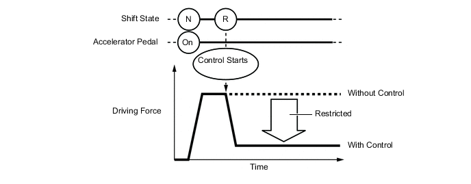
Control when Starting Off from a Parked Position Control Start Conditions (When all of the following conditions are met, control starts.)
-
Shift state is changed from P to D/M*, or P to R*.
*: Depending on the situation, the shift position cannot be changed.
-
Accelerator opening angle is approximately 1/5 or higher.
Control Operation Restricted the driving force so the vehicle speed and acceleration are at or below a certain level. Control Stop Conditions (Control stops when any of the conditions are met.)
-
Accelerator pedal is fully released.
-
Shift state is P or N.
Figure 2. Image of Control when Starting Off from a Parked Position
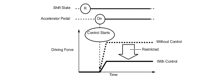
Control during Other Situations Control Start Conditions (When all of the following conditions are met, control starts.)
-
Shift state is changed from R to D/M, D/M to R, or N to R.
-
Accelerator opening angle is approximately 1/5 or higher.
Control Operation Restricts the driving force so the vehicle speed and acceleration are at or below a certain level. Control Stop Conditions (Control stops when any of the conditions are met.)
-
Accelerator pedal is fully released.
-
Shift state is P or N.
Figure 3. Image of Control during Other Situations
Tech Tips
-
The driving force restraint level differs in the above 2 situations.
-
During control while a shift operation is performed (from control start until the accelerator pedal is released), the system informs the driver of the control via the combination meter assembly and headup display*.
-
*: Models with headup display
-
-
-
Control during Reverse Operation
-
Responds to excessive depression of the accelerator pedal while operating in reverse.
-
Corrects driving force according to the road grade and steering angle.
Control Start Conditions (When all of the following conditions are met, control starts.)
-
Shift state is R.
-
Accelerator pedal is depressed excessively.
Control Operation Restricts the driving force so the vehicle speed and acceleration are at or below a certain level. Control Stop Conditions (Control stops when any of the conditions are met.)
-
Accelerator pedal is fully released.
-
Shift state is not R.
-
-
-
-
-
FUNCTION
-
EV Mode
-
EV mode is provided to reduce vehicle noise, such as when entering or leaving a garage, as well as reducing the production of exhaust gases in a garage. When the EV mode switch is operated by the driver, the hybrid vehicle control ECU assembly uses only MG2 to drive the vehicle if the operating conditions are met.
-
The available driving range during the EV mode varies in accordance with the driving conditions and the HV battery charge level. However, the range is usually between several hundred meters (several hundred yards) and approximately 1 km (0.6 miles). When all operating conditions are met, pressing the EV mode switch enters the EV mode, and the EV mode indicator will be illuminated. If any operating condition is not met and the EV mode switch is pressed, a message is displayed on the multi-information display to inform the driver that the EV mode switch operation is rejected, and the EV mode cannot be entered.
-
If any condition does not meet the operating conditions while the vehicle is traveling in EV mode, the EV mode indicator flashes 3 times and a buzzer sounds. When the EV mode has been automatically canceled, another message is displayed to indicate that the EV mode has been canceled.
Figure 4. LHD Models
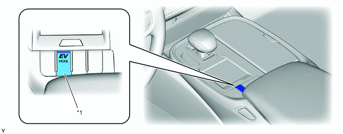
*1 EV Mode Switch - - Figure 5. RHD Models
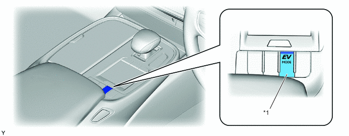
*1 EV Mode Switch - -
-
-
Drive Mode Select
-
The motive force characteristics for the accelerator opening angle can be changed through the selection of the drive mode according to driver preference.
-
The drive mode can be switched by turning the dial type drive mode select. In addition, the vehicle can be returned to Normal mode by pressing the drive mode select.
-
The drive mode is displayed under the tachometer on the combination meter assembly so that the driver can see the mode that they selected.
Figure 6. LHD Models
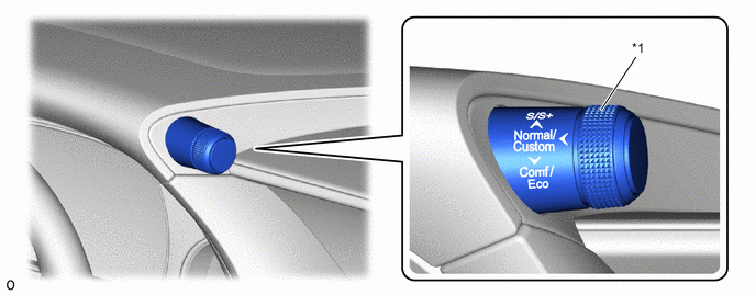
*1 Drive Mode Select - - Figure 7. RHD Models
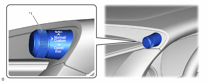
*1 Drive Mode Select - - -
The characteristics of each drive mode are as follows:
Drive Mode Outline Normal Mode This drive mode provides optimum driveability. Comfort Mode This mode adds AVS control to normal mode. The lower damping force range is mainly used, performing control to achieve a comfortable ride. Eco Mode The hybrid vehicle control ECU assembly optimizes fuel economy and driving performance by gently generating the motive force in comparison to the accelerator pedal operation. At the same time, the ECU supports eco driving by optimizing the air conditioning performance. Sport S Mode The hybrid vehicle control ECU assembly controls motive force in the intermediate area of accelerator pedal opening to a greater degree than that of Normal mode, thus improving acceleration performance. In addition, engine speed response performance has been improved in the high area of accelerator pedal opening, thus producing a sporty drive. Sport S+ Mode In addition to the control when in Sport S mode, the suspension control system and steering control system have been integrated to shift to Sport S+ mode, improved operability and stability have been aimed for even without losing comfort and a control which enables operation appropriate to the driver's intention is performed. Custom Mode Custom mode is a function where the control characteristics of each system (powertrain, chassis and air conditioning) can be freely selected and combined by the driver. Powertrain (Normal/Eco/Power), chassis (Normal/Sport/Comfort) and air conditioning (Normal/Eco) combinations can be freely selected to support the specific needs of the driver.
Tech Tips
Refer to the Repair Manual for the custom mode setting method.
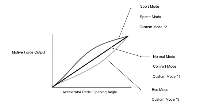
*1: When powertrain is set to "Normal"
*2: When powertrain is set to "Power"
*3: When powertrain is set to "Eco"
-
-
Snow Mode Control*
*: Models with Snow mode
-
The Snow mode can be selected by operating the Snow mode switch.
Figure 8. LHD Models
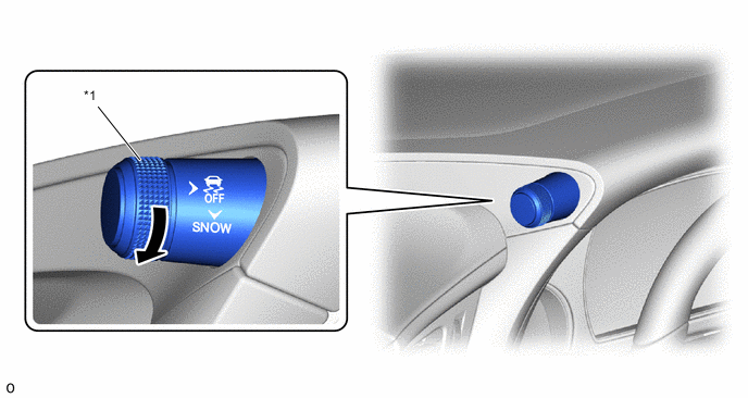
*1 Snow Mode Switch - - Figure 9. RHD Models
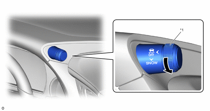
*1 Snow Mode Switch - - -
When the Snow mode is selected, the hybrid vehicle control ECU assembly improves starting-off performance and acceleration performance on slippery road surfaces such as snow on which the wheels may spin by controlling to restrain motive force more than when in Normal mode.
-
When Snow mode control is activated, the motive force that changes in accordance with the accelerator pedal operation is controlled to be smaller than Normal mode around the accelerator pedal angle which causes the wheels to slip easily, achieving enhanced accelerator pedal controllability.
Figure 10. Motive Force Output Characteristics
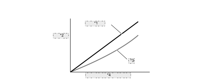
*1 Normal Mode *2 Motive Force Output *3 SNOW Mode *4 Accelerator Pedal Opening
-
-
-
FAIL-SAFE
-
When a malfunction has been detected, depending on the type of malfunction, the standard values in the hybrid vehicle control ECU assembly are used to continue the control mode or to disable the hybrid system.
-
-
DIAGNOSIS
-
In the hybrid system, if the hybrid vehicle control ECU assembly or Motor Generator ECU (MG ECU) detects a malfunction, the hybrid vehicle control ECU assembly records the fault and memorizes the information that relates to the fault. To inform the driver of the malfunction, the hybrid vehicle control ECU assembly illuminates or blinks the MIL and master warning light, and displays a message on the multi-information display.
-
The hybrid vehicle control ECU assembly will store the respective DTCs of the malfunctions.
-
The DTCs can be accessed by using the TechStream (GTS).
-
For details, refer to the Repair Manual.
-