HYBRID CONTROL SYSTEM
Figure 1. LHD Models
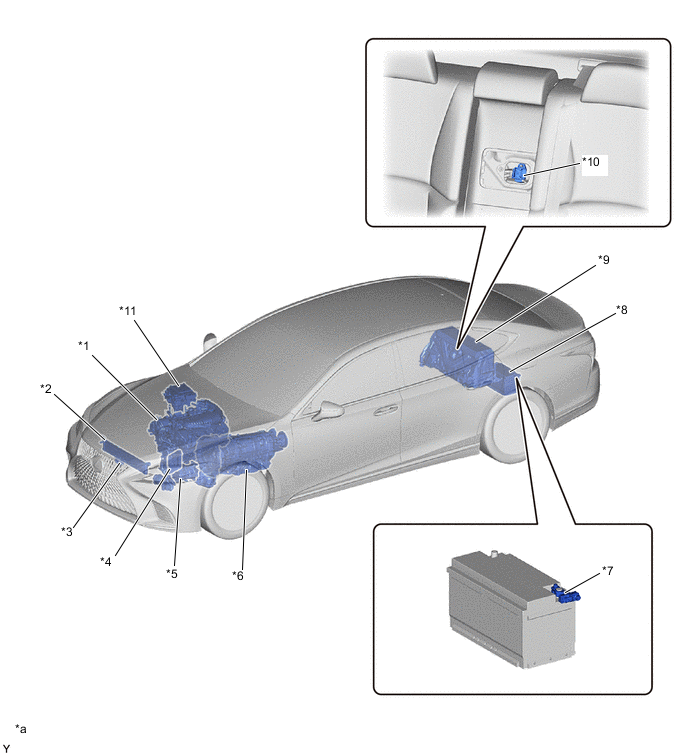
| *1 | 8GR-FXS Engine | *2 | Radiator Assembly |
| *3 | Inverter Water Pump with Motor Assembly | *4 | ECM |
| *5 | Compressor with Motor Assembly | *6 | L310 Hybrid Transmission (Hybrid Vehicle Transmission Assembly)
|
| *7 | Battery State Sensor Assembly | *8 | Auxiliary Battery |
| *9 | HV Battery (HV Supply Battery Assembly) | *10 | Service Plug Grip |
| *11 | Inverter with Converter Assembly
|
- | - |
| *a | The illustrations shown are examples only. | - | - |
Figure 2. RHD Models
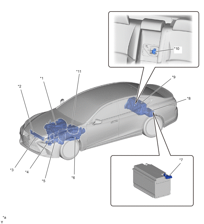
| *1 | 8GR-FXS Engine | *2 | Radiator Assembly |
| *3 | Inverter Water Pump with Motor Assembly | *4 | ECM |
| *5 | Compressor with Motor Assembly | *6 | L310 Hybrid Transmission (Hybrid Vehicle Transmission Assembly)
|
| *7 | Battery State Sensor Assembly | *8 | Auxiliary Battery |
| *9 | HV Battery (HV Supply Battery Assembly) | *10 | Service Plug Grip |
| *11 | Inverter with Converter Assembly
|
- | - |
| *a | The illustrations shown are examples only. | - | - |
Figure 3. LHD Models
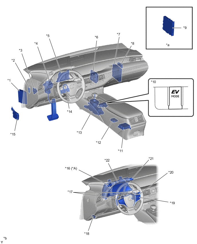
| *A | Models for SNOW mode | - | - |
| *1 | Skid Control ECU Assembly | *2 | Stop Light Switch Assembly |
| *3 | Brake Pedal Stroke Sensor Assembly | *4 | Accelerator Pedal Sensor Assembly |
| *5 | Air Conditioning Amplifier Assembly | *6 | Shift Control ECU |
| *7 | Hybrid Vehicle Control ECU Assembly | *8 | Central Gateway ECU (Network Gateway ECU) |
| *9 | Certification ECU (Smart Key ECU Assembly) | *10 | EV Mode Switch (Integration Control and Panel Assembly) |
| *11 | Airbag ECU Assembly | *12 | Yawrate Sensor |
| *13 | Transmission Floor Shift Assembly
|
*14 | Steering Sensor |
| *15 | Driving Support ECU Assembly | *16 | SNOW Switch (Satellite Switch Set) |
| *17 | Paddle Shift Switch (Transmission Shift Switch Assembly) | *18 | DLC3 |
| *19 | Steering Pad Switch Assembly (for Cruise Control) | *20 | Power Switch (Push Start Switch) |
| *21 | Drive Mode Select (Satellite Switch Set) | *22 | Combination Meter Assembly |
| *a | Refer to the Service Bulletin for the installation position of the parts. | *b | The illustrations shown are examples only. |
Figure 4. RHD Models
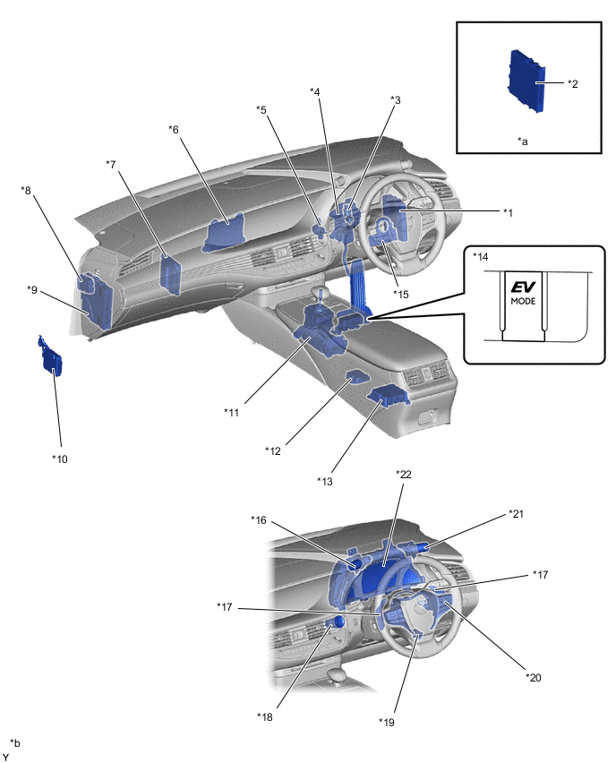
| *1 | Skid Control ECU Assembly | *2 | Certification ECU (Smart Key ECU Assembly) |
| *3 | Stop Light Switch Assembly | *4 | Accelerator Pedal Sensor Assembly |
| *5 | Brake Pedal Stroke Sensor Assembly | *6 | Air Conditioning Amplifier Assembly |
| *7 | Shift Control ECU | *8 | Central Gateway ECU (Network Gateway ECU) |
| *9 | Hybrid Vehicle Control ECU Assembly | *10 | Driving Support ECU Assembly |
| *11 | Transmission Floor Shift Assembly
|
*12 | Yawrate Sensor |
| *13 | Airbag ECU Assembly | *14 | EV Mode Switch (Integration Control and Panel Assembly) |
| *15 | Steering Sensor | *16 | Drive Mode Select (Satellite Switch Set) |
| *17 | Paddle Shift Switch (Transmission Shift Switch Assembly) | *18 | Power Switch (Push Start Switch) |
| *19 | DLC3 | *20 | Steering Pad Switch Assembly (for Cruise Control) |
| *21 | SNOW Switch (Satellite Switch Set) | *22 | Combination Meter Assembly |
| *a | Refer to the Service Bulletin for the installation position of the parts. | *b | The illustrations shown are examples only. |