LIGHTING SYSTEM
-
FUNCTION OF MAIN COMPONENTS
Component Function Light Control LED ECU RH Receives signals from various sensors and controls the headlight illuminations based on the conditions of the vehicle and surroundings. Light Control LED ECU LH Headlight ECU Sub-assembly RH
-
Receives signals from various sensors and controls the headlight brightness and illumination area based on the conditions of the vehicle and surroundings.
-
Sends adaptive high beam system control request signals to the light control LED ECU.
-
Stores DTCs when a malfunction is detected in the adaptive high beam system.
Headlight ECU Sub-assembly LH Camera Sensor (Forward Recognition Camera)
-
Captures an image of the area in front of the vehicle and uses the image to determine the position of preceding and oncoming vehicles and to determine the brightness of the surrounding area. This data is then sent to the headlight ECU sub-assembly LH via CAN communication.
-
Transmits an operation signal to the camera heater.
Turn Signal Switch Light Control Switch Sends the light control switch signals to the steering sensor. Dimmer Switch Sends the dimmer switch signals to the steering sensor. Auto High Beam Switch Sends the auto high beam main switch signals to the steering sensor. Steering Sensor Sends the light control switch, dimmer switch and auto high beam main switch signals to the main body ECU (multiplex network body ECU). Main Body ECU (Multiplex Network Body ECU)
-
Receives signals from the steering sensor and automatic light control sensor.
-
Controls the headlight ECU sub-assembly LH and headlight ECU sub-assembly RH based on signals from various sensors and switches.
-
Sends illumination request signals for the adaptive high beam indicator and high beam indicator to the combination meter assembly according to the operation condition of the headlight system.
Automatic Light Control Sensor Detects the ambient light level and transmits a signal to the main body ECU (multiplex network body ECU). Skid Control ECU Sends the vehicle speed signal to the combination meter assembly. Combination Meter Assembly
-
Sends the vehicle speed signal to the main body ECU (multiplex network body ECU).
-
Illuminates the adaptive high beam indicator to inform the driver when the adaptive high beam system is activated.
-
Illuminates the high beam indicator light to inform the driver when the high beams are on.
Suspension Control ECU*1 Sends the vehicle height value signal to the headlight ECU sub-assembly LH.*1 Absorber Control ECU*2 Sends the vehicle height value signal to the headlight ECU sub-assembly LH.*3 Rear Height Control Sensor Sub-assembly LH Detects the height of the vehicle and sends the signal to the headlight ECU sub-assembly LH.*4 ECM Sends the shift position signals to the headlight ECU sub-assembly LH. Camera Heater (Forward Recognition Hood with Heater Sub-assembly) The camera heater is heated according to signals from the camera sensor (forward recognition camera). Central Gateway ECU (Network Gateway ECU) Relays the signal between the CAN communication lines. DLC3 The Global TechStream (GTS) can be connected to read the Diagnostic Trouble Codes (DTCs) of malfunctions. *1: Models with air suspension system
*2: Models with AVS system
*3: Models with AVS system (without air suspension system)
*4: Models without AVS system and air suspension system
-
-
SYSTEM CONTROL
-
Operation Conditions of the Adaptive High Beam System
-
The adaptive high beam system operates when all of the following conditions are met. While the adaptive high beam system is on, the adaptive high beam indicator light illuminates.
-
The engine switch is on (IG).
-
The light control switch is in the HEAD position and AUTO position and the headlights are operating.
-
The dimmer switch is in the HI position.
-
The adaptive high beam switch is on. *1
-
The vehicle speed is approximately 15 km/h or more.*2, *4
-
The vehicle speed is approximately 60 km/h or more.*3, *4
Tech Tips
*1: When the adaptive high beam switch is turned on while the headlights are not illuminated or the dimmer switch in a position other than HI, a message is displayed on the multi-information display.
*2: Except models for Europe
*3: Models for Europe
*4: The cornering lights illuminate when the vehicle speed reaches approximately 3 km/h or more.
-
-
-
High Beam Light Distribution Control Function
-
In high beam light distribution control function, the headlight ECU sub-assemblies control the brightness and illumination area of the high beam.
-
The high beam light distribution control function, changes the intensity and illumination area according to 4 vehicle speed ranges:
Illumination Mode Description of Function Vehicle Speed Low Speed Mode (Town Mode)
-
Widens the illuminated area.
-
The brightness of the headlights is adjusted to ensure that pedestrians are visible while not being dazzled.
-
Reduces illumination of the side of the road.
-
15 - 30 km/h (10 - 25 mph)*1
-
-*2
Normal Mode
-
At medium speeds, the illuminated area in front of the vehicle is extended and necessary areas to the left and right of the vehicle are illuminated.
-
Illuminates the outer LED unit to enhance the intensity of the headlights.
-
Reduces the light distribution at the center of the high beams when driving in rainy weather to prevent glare from oncoming vehicles caused by camera recognition delays.
-
30 - 80 km/h (25 - 50 mph)*1
-
60 - 120 km/h
(38 - 75 mph)*2
High Speed Mode 1
-
The illuminated area in front of the vehicle is narrowed.
-
Adjusts the high beams to ensure visibility far in front of the vehicle.
-
Reduces the light distribution at the center of the high beams when driving in rainy weather to prevent glare from oncoming vehicles caused by camera recognition delays.
-
80 - 120 km/h (50 - 75 mph)*1
-
120 - 140 km/h
(75 - 90 mph)*2
High Speed Mode 2
-
The illuminated area in front of the vehicle is narrowed.
-
Illuminates the outer LED unit to enhance the intensity of the headlights.
-
Reduces the light distribution at the center of the high beams when driving in rainy weather to prevent glare from oncoming vehicles caused by camera recognition delays.
-
Adjusts the high beams to ensure visibility far in front of the vehicle.
-
120 km/h (75 mph) or more*1
-
140 km/h (90 mph) or more*2
*1: Except models for Europe
*2: Models for Europe
Figure 1. Low Speed Mode (Town Mode)
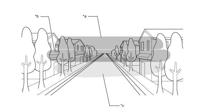
*a Area Illuminated by High Beams (Upper Row) *b Area Illuminated by High Beams (Lower Row) *c Area Illuminated by Low Beams - - Figure 2. Normal Mode
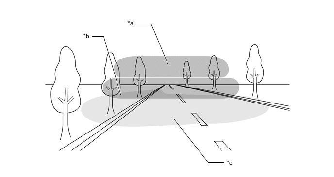
*a Area Illuminated by High Beams (Upper Row) *b Area Illuminated by High Beams (Lower Row) *c Area Illuminated by Low Beams - - Figure 3. High Speed Mode 1
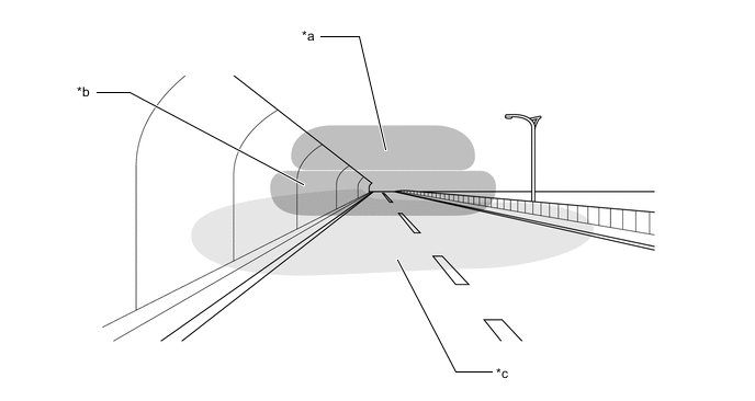
*a Area Illuminated by High Beams (Upper Row) *b Area Illuminated by High Beams (Lower Row) *c Area Illuminated by Low Beams - - Figure 4. High Speed Mode 2
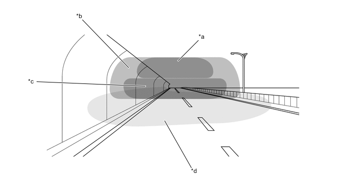
*a Area Illuminated by High Beams (Upper Row) *b Area Illuminated by High Beams (Outside) *c Area Illuminated by High Beams (Lower Row) *d Area Illuminated by Low Beams -
-
-
Light Disable Control Function
-
The light disable control function dims LEDs in the high beam headlight accordingly when the forward recognition camera assembly detects a preceding vehicle or an oncoming vehicle.
-
The light control LED ECU and LED unit enable the LEDs of the headlight assembly to be dimmed independently as necessary.
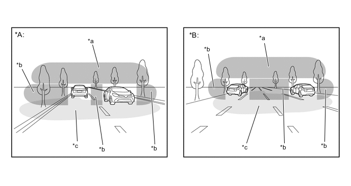
*A When driving on road with one lane in each direction *B When driving on a multi-lane road *a Area Illuminated by High Beams (Upper Row) *b Area Illuminated by High Beams (Lower Row) *c Area Illuminated by Low Beams - -
-
-
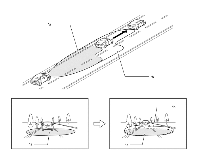
Headlight Swivel Control Function
-
The headlight swivel control function adjusts the brightness of headlights while turning a corner to ensure excellent visibility.
*a Area Illuminated by High Beams (Upper Row) *b Area Illuminated by High Beams (Lower Row) *c Area Illuminated by Low Beams - -
-
-
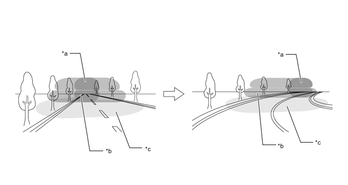
Cut-off Line Tilt Control Function
-
The cut-off line tilt function controls the leveling motor built into the headlight assembly to optimize the illumination area of the low beams in accordance with the distance to the preceding vehicle detected by the forward recognition camera.
*a Illumination Area of Low Beams without Control *b Illumination Area of Low Beams during Control
-
-
Reduced Speed Control Function
-
The cornering lights are illuminated when reducing speed to improve visibility to each side.
-
-
-
FUNCTION
-
The adaptive high beam system operates when the auto high beam switch is on, the light control switch is in the HEAD or AUTO position and the dimmer switch is set to HI. The adaptive high beam system uses the camera sensor to detect the lights of oncoming vehicles and the taillights of preceding vehicles and to determine the brightness of the surrounding area in order to select which LEDs of the LED array to illuminate.
-
The headlight ECU sub-assemblies control the adaptive high beam system.
-
When the adaptive high beam system is on, the adaptive high beam indicator light in the combination meter assembly illuminates.
-
-
FAIL-SAFE
-
The headlight ECU sub-assemblies prohibit operation of the adaptive high beam system if a malfunction is detected in the system.
-