LIGHTING SYSTEM
-
FUNCTION OF MAIN COMPONENTS
Component Function Headlight ECU Sub-assembly RH Receives the headlight control signal from the main body ECU (multiplex network body ECU) and changes between the high beams and low beams. Headlight ECU Sub-assembly LH Camera Sensor (Forward Recognition Camera) Determines when to turn the high beams on and off after identifying the lights of oncoming vehicles, preceding vehicles and other lights from the picture information of its camera sensor. Then, the sensor sends high beam request signals to the main body ECU (multiplex network body ECU). Main Body ECU (Multiplex Network Body ECU) Receives each sensor and switch condition and illuminates or turns off the lights. Automatic Light Control Sensor Detects the ambient light level and transmits a signal to the main body ECU (multiplex network body ECU). Turn Signal Switch Light Control Switch Sends the light control switch signals to the steering sensor. Dimmer Switch Sends the dimmer switch signals to the steering sensor. Auto High Beam Switch Sends the auto high beam switch signals to the steering sensor. Steering Sensor Sends the light control switch, dimmer switch and auto high beam main switch signals to the main body ECU (multiplex network body ECU). Skid Control ECU Assembly*1 Sends the vehicle speed signal to the combination meter assembly. Skid Control ECU*2 Combination Meter Assembly
-
Sends the vehicle speed signal to the main body ECU (multiplex network body ECU).
-
Illuminates the automatic high beam indicator to inform the driver when the automatic high beam system is activated.
-
Illuminates the high beam indicator light to inform the driver when the high beams are on.
Camera Heater (Forward Recognition Hood with Heater Sub-assembly) The camera heater is heated according to signals from the camera sensor (forward recognition camera). Central Gateway ECU (Network Gateway ECU) Relays the signal between the CAN communication lines. DLC3 The Global TechStream (GTS) can be connected to read the Diagnostic Trouble Codes (DTCs) of malfunctions. *1: Models with electronically controlled brake system
*2: Models with vacuum brake booster
-
-
SYSTEM CONTROL
Function Operation Condition Active When all of the following conditions are met, the automatic high beam system is activated and the automatic high beam indicator light turns on:
-
The engine switch is on (IG).
-
The light control switch is in the AUTO or HEAD position and the low beam headlights are on.
-
The dimmer switch is in the high beam position.
-
The auto high beam switch is ON.
-
The shift position is in any position other than R.
High Beams on When all of the following conditions are met, the automatic high beam system turns on the high beams after a short delay:
-
Vehicle speed is more than approximately 40 km/h (25 mph).*1
-
Vehicle speed is more than approximately 30 km/h (19 mph).*2
-
The area in front of the vehicle is dark.
-
No oncoming vehicles are present with the headlights on.
-
No preceding vehicles are present with the taillights on.
-
Few streetlights are present along the street ahead.
High Beams off When any of the following conditions is met, the automatic high beam system turns off the high beams after a short delay:
-
Vehicle speed is less than approximately 30 km/h (19 mph).*1
-
Vehicle speed is less than approximately 25 km/h (16 mph).*2
-
The area in front of the vehicle is not dark.
-
An oncoming vehicle with headlights on is detected.
-
A preceding vehicle with taillights on is detected.
-
Several streetlights are present along the street ahead.
*1: Models for Europe
*2: Except Models for Europe
-
-
FUNCTION
-
When passing an oncoming vehicle:
-
The automatic high beam system turns off the high beams before an oncoming vehicle comes within approximately 800 m (2625 ft.).
-
When an oncoming vehicle passes out of camera sensor range, the automatic high beam system turns the high beams on after a short delay.
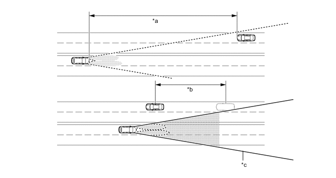
*a 800 m (2625 ft.) *b Delay *c Camera Sensor Angle - - Tech Tips
-
The detection distance varies depending on detected objects.
-
The timing of turning on and off the high beams varies depending on the intensity of oncoming (and preceding) vehicle lights.
-
-
When passing a preceding vehicle:
-
When approaching a preceding vehicle, the automatic high beam system turns off the high beams approximately 600 m (1969 ft.) before reaching it.
-
When a preceding vehicle passes out of camera sensor range, the automatic high beam system turns the high beams on after a short delay.
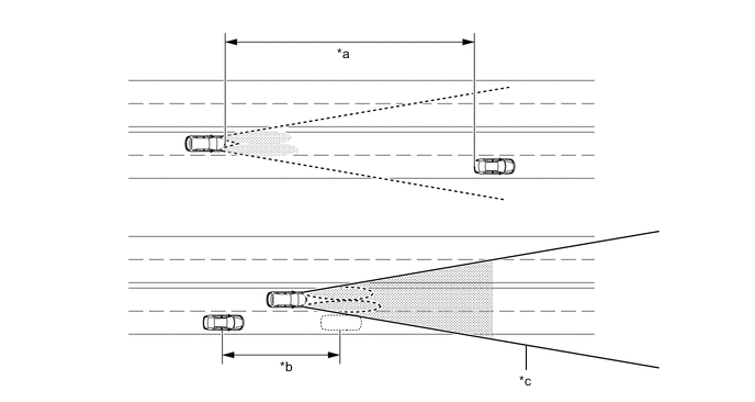
*a 600 m (1969 ft.) *b Delay *c Camera Sensor Angle - - Tech Tips
The timing of turning on and off the high beams varies depending on the intensity of the preceding vehicle lights.
-
-
-
DIAGNOSIS
-
In order to make system inspections easier to perform, a diagnosis function is used in consideration of serviceability. The Diagnostic Trouble Codes (DTCs) of malfunctions can be read by connecting the Global TechStream (GTS). For details, refer to the Repair Manual.
-