DOOR CLOSER SYSTEM
-
CONSTRUCTION
-
Door Closer Assembly
-
The door closer assembly is composed of a door lock mechanism and a door closer mechanism.
-
The door lock mechanism performs normal door lock operations. The door closer mechanism reduces the drive force of the door closer motor using the planetary gear, rotates the output shaft and pulls the close cable via the output lever. As a result, the latch lever in the door lock mechanism is moved to rotate the latch.
-
Position detection switches (half/full latch switch, temporary stop switch, pawl switch, initial position switch and handle switch) are built into the door lock mechanism.
Position Detection Switch Function Component Function Half/Full Latch Switch Determines the locations of fully-closed and half-shut doors and outputs them to the multiplex network door ECU. Temporary Stop Switch Determines the temporary stop position of the door closer system and outputs it to the multiplex network door ECU. Pawl Switch Detects the status of the pawl and outputs it to the multiplex network door ECU. Initial Position Switch Detects the initial position of the door closer motor and outputs it to the multiplex network door ECU. Handle Switch Detects the status of the outside or inside handle and outputs it to the multiplex network door ECU. Figure 1. Front Door Closer Assembly
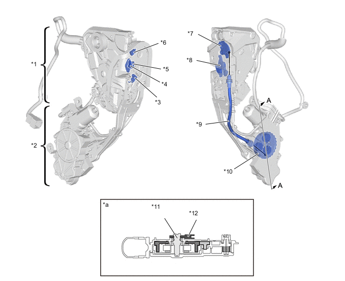
*1 Door Lock Mechanism
-
Handle Switch
*2 Door Closer Mechanism
-
Door Closer Motor
*3 Pawl Switch *4 Temporary Stop Switch *5 Half/Full Latch Switch *6 Initial Position Switch *7 Latch Lever *8 Latch *9 Close Cable *10 Planetary Gear *11 Output Shaft *12 Output Lever *a A - A Cross Section - - Figure 2. Rear Door Closer Assembly
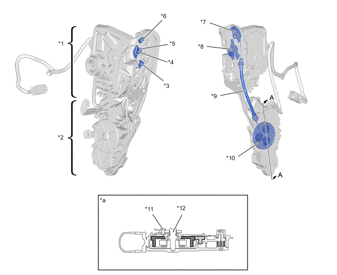
*1 Door Lock Mechanism
-
Handle Switch
*2 Door Closer Mechanism
-
Door Closer Motor
*3 Pawl Switch *4 Temporary Stop Switch *5 Half/Full Latch Switch *6 Initial Position Switch *7 Latch Lever *8 Latch *9 Close Cable *10 Planetary Gear *11 Output Lever *12 Output Shaft *a A - A Cross Section - - -
-
-
Mechanical Cancel Mechanism
-
By operating the outside or inside door handle during a door close operation, the drive power from the door closer motor is mechanically stopped to stop the system operation.
-
When the door handle is operated, the cancel lever is pulled via the cable. As a result, the cancel gear and ring gear are disengaged and the ring gear is completely released. The pinion gears become idle and the drive power to the output shaft is stopped.
-
When the outside or inside door handle is operated during a close operation, the mechanical cancel function operates and receives a signal from the handle switch at the same time. As a result, the door closer motor stops.
Tech Tips
When the inside door handle is operated with the child lock for the rear seat on, a cancel operation is not performed.
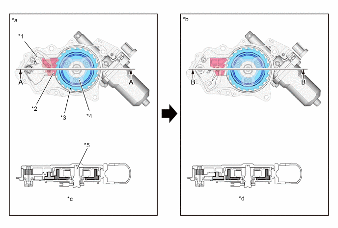
*1 Cancel Lever *2 Cancel Gear *3 Ring Gear *4 Pinion Gear *5 Output Shaft - - *a When Closer Operation Performed *b When Closer Mechanical Cancel Operation Performed *c A - A Cross Section *d B - B Cross Section
-
-
-
OPERATION
-
Close Operation
-
When all the following conditions are met after the half/full latch switch has been off and the temporary stop switch has been on, forward rotation operation will commence after approximately 0.7 seconds:
Forward Rotation Operation Commencement Condition
-
Half/full latch switch is turned from off to on.
-
Temporary stop switch is on.
-
Pawl switch is turned from on to off.
-
Initial position switch is off.
-
Handle switch is off.
-
-
When the temporary stop switch is turned off after the forward rotation operation starts, the door closer motor will be stopped for approximately 1 second.
Forward Rotation Operation Stop Condition
-
Temporary stop switch is turned from on to off.
-
-
When all the following conditions are met, forward rotation operation will complete:
Forward Rotation Operation Completion Condition
-
Half/full latch switch is off.
-
Temporary stop switch is off.
-
Pawl switch is turned from on to off.
-
Initial position switch is on.
-
-
The reverse rotation operation starts approximately 0.1 seconds after the reverse rotation operation completion conditions are met. When either of the following conditions is met, the reverse rotation operation will complete:
Reverse Rotation Operation Completion Condition
-
Initial position switch is off.
-
Approx. 1.5 seconds have passed.
-
-
-
Close Operation Cancellation
-
When any of the following conditions is met, the close operation will be canceled.
Close Operation Cancellation Condition
-
Handle switch is on.
-
Half/full latch switch is off and temporary stop switch is on.
-
A current has been continuously applied to the motor for longer than a predetermined amount of time.
-
-
-