AIR CONDITIONING SYSTEM
-
CONSTRUCTION
-
An air conditioning unit that is compatible with left and right independent temperature control or multi-zone (4-ZONE) climate control is used.
-
The air conditioning unit consists of the No. 1 cooler evaporator sub-assembly, heater radiator unit sub-assembly, servo motors, evaporator temperature sensor (No. 1 cooler thermistor) and blower with fan motor sub-assembly.
-
A Beneficial cold storage (CS) type evaporator*1 or revolutionary super-slim (RS) type evaporator*2 is used.
-
*1: Models with stop and start system
-
*2: Models without stop and start system
-
-
A Straight Flow Aluminum-II (SFA-II) heater core that is compact and offers advanced performance is used.
-
A pollen and odor-removing type clean air filter (air refiner element) is provided as standard equipment.
Figure 1. Air Conditioning Unit Layout Parts Location
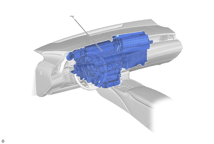
*1 Air Conditioning Unit Assembly - - Figure 2. Duct Layout Parts Location
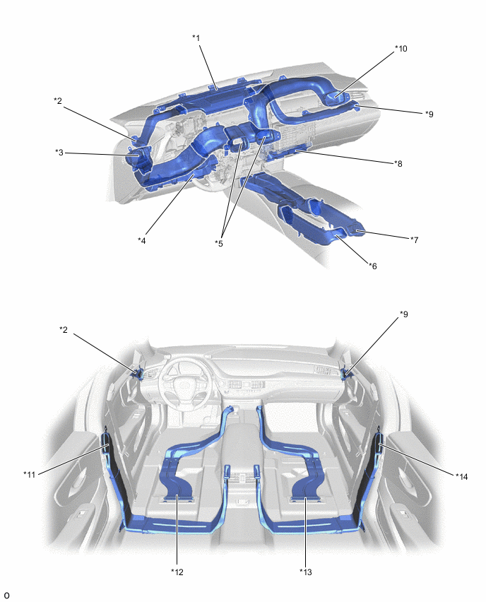
*1 Front Defroster Duct *2 Driver Side Side Defroster Duct *3 Driver Side Side Register Duct *4 Driver Side Footwell Duct *5 Center Register Duct *6 Rear Passenger Left Side Center Register Duct *7 Rear Passenger Right Side Center Register Duct *8 Front Passenger Side Footwell Duct *9 Front Passenger Side Side Defroster Duct *10 Front Passenger Side Side Register Duct *11 Rear Passenger Left Side Side Register Duct *12 Rear Passenger Left Side Footwell Duct *13 Rear Passenger Right Side Footwell Duct *14 Rear Passenger Right Side Side Register Duct
-
-
OPERATION
-
Mode Position and Door Operation
Figure 3. Models with Multi-zone (4-ZONE) Climate Control
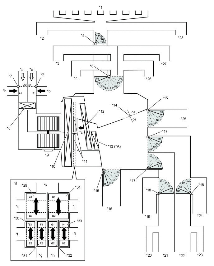
*A Models with PTC Heater - - *1 Front Defroster Duct *2 Driver Side Side Defroster Duct *3 Driver Side Side Register Duct *4 Driver Side Center Register Duct *5 DEF Mode Door Switching Servo Motor *6 FACE Mode Door Switching Servo Motor *7 Fresh / Recirculation Mode Door Switching Servo Motor *8 Air Refiner Element (Clean Air Filter) *9 Blower Motor with Fan Sub-assembly *10 No. 1 Cooler Evaporator Sub-assembly *11 Air Mix Servo Motor *12 Heater Radiator Unit Sub-assembly *13 PTC Heater (Quick Heater Assembly) *14 Inside-and-outside Dual Air Layer Switching Servo Motor *15 FOOT Mode Door Switching Servo Motor *16 Driver Side Footwell Duct *17 Rear Passenger Side FACE Mode Door Switching Servo Motor *18 Rear Passenger Side FOOT Mode Door Switching Servo Motor *19 Rear Passenger Left Side Footwell Duct *20 Rear Passenger Left Side Side Register Duct *21 Rear Passenger Left Side Register Duct *22 Rear Passenger Right Side Register Duct *23 Rear Passenger Right Side Side Register Duct *24 Rear Passenger Right Side Footwell Duct *25 Front Passenger Side Footwell Duct *26 Front Passenger Side Center Register Duct *27 Front Passenger Side Side Register Duct *28 Front Passenger Side Side Defroster Duct *29 Driver Side Upper Layer Air Mix Servo Motor *30 Driver Side Lower Layer Air Mix Servo Motor *31 Rear passenger Left Side Air Mix Servo Motor *32 Rear Passenger Right Side Air Mix Servo Motor *33 Front Passenger Side Lower Layer Air Mix Servo Motor *34 Front Passenger Side Upper Layer Air Mix Servo Motor *a Fresh Air *b Recirculation Air *c Illustration Image View from [A] *d [A] View *e Driver Side Register Duct *f Driver Side Footwell Duct *g Rear Left Side Duct *h Rear Right Side Duct *i Front Passenger Side Footwell Duct *j Front Passenger Side Register Duct *k Defroster Duct - - Figure 4. Models with Left and Right Independent Temperature Control
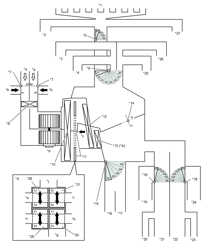
*A Models with PTC Heater - - *1 Front Defroster Duct *2 Driver Side Side Defroster Duct *3 Driver Side Side Register Duct *4 Driver Side Center Register Duct *5 DEF Mode Door Switching Servo Motor *6 FACE Mode Door Switching Servo Motor *7 Fresh / Recirculation Mode Door Switching Servo Motor *8 Air Refiner Element (Clean Air Filter) *9 Blower Motor with Fan Sub-assembly *10 No. 1 Cooler Evaporator Sub-assembly *11 Air Mix Servo Motor *12 Heater Radiator Unit Sub-assembly *13 PTC Heater (Quick Heater Assembly) *14 Inside-and-outside Dual Air Layer Switching Servo Motor *15 FOOT Mode Door Switching Servo Motor *16 Driver Side Footwell Duct *17 Front Passenger Side Footwell Duct *18 Rear Mode Door Switching Servo Motor *19 Rear Passenger Left Side Footwell Duct *20 Rear Passenger Left Side Side Register Duct *21 Rear Passenger Left Side Center Register Duct *22 Rear Passenger Right Side Center Register Duct *23 Rear Passenger Right Side Side Register Duct *24 Rear Passenger Right Side Footwell Duct *25 Front Passenger Side Center Register Duct *26 Front Passenger Side Side Register Duct *27 Front Passenger Side Side Register Duct *28 Driver Side Upper Layer Air Mix Servo Motor *29 Driver Side Lower Layer Air Mix Servo Motor *30 Front Passenger Side Lower Layer Air Mix Servo Motor *31 Front Passenger Side Upper Layer Air Mix Servo Motor - - *a Fresh Air *b Recirculation Air *c Illustration Image View from [A] *d [A] View *e Driver Side Register Duct *f Driver Side Footwell Duct *g Front Passenger Side Footwell Duct *h Rear Duct *i Front Passenger Side Register Duct *j Defroster Duct Mode Position and Damper Operation Control Damper Operation Position Damper Position*1 Damper Position*2 Operation Air Inlet Control Damper FRESH A2
B2
Allows fresh air to enter. RECIRCULATION A1
B1
Causes internal air to recirculate. Inside-and-outside Dual Air Layer Control Door - (Auto Control) O1 - O2 I1 - I2 Separates or integrates the upper layer and lower layer in response to the control conditions to control the inside-and-outside dual air layers. Air Mix Control Damper MAX COLD to MAX HOT Temperature Setting C1 - C2
D1 - D2
E1- E2
F1 - F2
G1 - G2*2
H1 - H2*2
Separates or integrates the upper layer and lower layer in response to the control conditions to control the inside-and-outside dual air layers. Air Outlet Control Damper FACE U I5
J4
K4
L1
M1
N5
P1
Q4
G4
H1
J1
K4
Blows air out from the following registers.
-
Driver Side Registers
-
Front Passenger Side Registers
-
Rear Passenger Right Side Registers
-
Rear Passenger Left Side Registers
FACE L I4
J3
K3
L1
M1
N4
P1
Q4
G5
H2
J1
K4
-
Blows air out from the following registers when FACE L mode is turned on by auto control.
-
Driver Side Registers
-
Front Passenger Side Registers
-
Rear Passenger Right Side Registers
-
Rear Passenger Left Side Registers
-
Blows small amounts of air out from the following registers.
-
Driver Side Footwell Register
-
Front Passenger Side Footwell Register
-
Rear Passenger Right Side Footwell Register
-
Rear Passenger Left Side Footwell Register
FACE R I5
J4
K4
L1
M1
N5
P2
Q3
G4
H1
J2
K4
Blows air out from the following registers when FACE R mode is turned on by auto control.
-
Driver Side Registers
-
Front Passenger Side Registers
-
Rear Passenger Right Side Registers
-
Rear Passenger Left Side Registers
BI-LEVEL I2
J1
K1
L2
M2
N2
P3
Q4
G2
H3
J3
K4
-
Blows air out from the following registers.
-
Driver Side Registers
-
Driver Side Footwell Register
-
Front Passenger Side Registers
-
Front Passenger Side Footwell Register
-
Rear Passenger Right Side Registers
-
Rear Passenger Right Side Footwell Register
-
Rear Passenger Left Side Registers
-
Rear Passenger Left Side Footwell Register
-
May blow air out from the following registers if necessary.
-
Driver Side Defrosters
-
Front Passenger Side Defrosters
FOOT D I2
J1
K1
L3
M3
N2
P6
Q2
G2
H4
J6
K2
-
Blows air out from the following registers when FOOT D mode is turned on by auto control.
-
Driver Side Footwell Register
-
Front Passenger Side Footwell Register
-
Rear Passenger Right Side Footwell Register
-
Rear Passenger Left Side Footwell Register
-
Blows small amounts of air out from the following registers.
-
Driver Side Defrosters
-
Front Passenger Side Defrosters
FOOT R I2
J1
K1
L3
M3
N2
P7
Q3
G2
H4
J7
K3
-
Blows air out from the following registers.
-
Driver Side Footwell Register
-
Front Passenger Side Footwell Register
-
Rear Passenger Right Side Footwell Register
-
Rear Passenger Left Side Footwell Register
-
Blows small amounts of air out from the following registers.
-
Driver Side Registers
-
Driver Side Defrosters
-
Front Passenger Side Registers
-
Front Passenger Side Defrosters
-
Rear Passenger Right Side Registers
-
Rear Passenger Left Side Registers
FOOT F I1
J1
K1
L3
M3
N1
P5
Q3
G1
H4
J5
K3
-
Blows air out from the following registers when FOOT F mode is turned on by auto control.
-
Driver Side Footwell Register
-
Passenger Side Footwell Register
-
Blows small amounts of air out from the following registers.
-
Driver Side Registers
-
Driver Side Defrosters
-
Front Passenger Side Registers
-
Front Passenger Side Defrosters
-
Rear Passenger Right Side Registers
-
Rear Passenger Right Side Footwell Register
-
Rear Passenger Left Side Registers
-
Rear Passenger Left Side Footwell Register
FOOT/DEF I3
J2
K2
L3
M3
N3
P4
Q1
G3
H5
J4
K1
-
Blows air out from the following registers.
-
Driver Side Footwell Register
-
Driver Side Defrosters
-
Passenger Side Footwell Register
-
Front Passenger Side Defrosters
-
Blows small amounts of air out from the following registers.
-
Driver Side Registers
-
Front Passenger Side Registers
-
Rear Passenger Right Side Registers
-
Rear Passenger Right Side Footwell Register
-
Rear Passenger Left Side Registers
-
Rear Passenger Left Side Footwell Register
DEF I5
J4
K4
L4
M4
P8
Q1
G4
H6
J8
K1
Blows air out from the following registers.
-
Driver Side Defrosters
-
Front Passenger Side Defrosters
*1: Models with multi-zone (4-ZONE) climate control
*2: Models with left and right independent temperature control
-
-
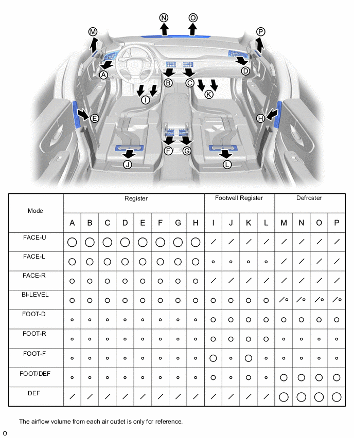
Air Outlets and Airflow Volume (for All Seat Control Modes)
-
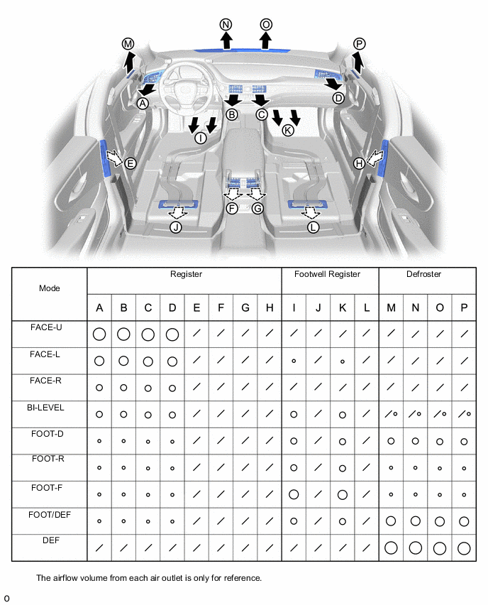
Air Outlets and Airflow Volume (for Front Seat Control Modes)
-
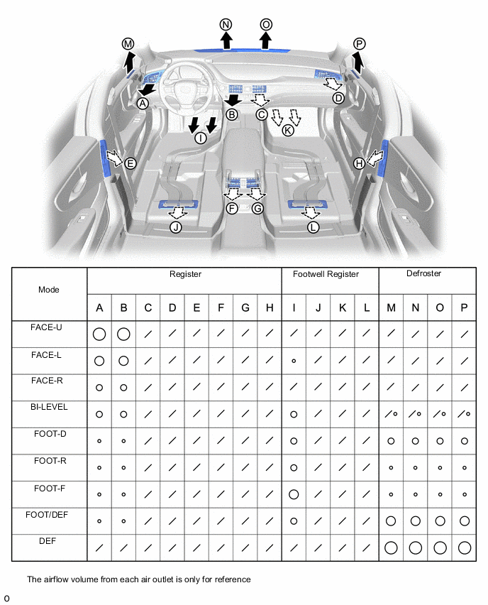
Air Outlets and Airflow Volume (for Driver Seat Control Modes)
-