CLIMATE CONTROL SEAT SYSTEM
-
SYSTEM CONTROL
-
If the auxiliary battery voltage is low, the climate control seat system may not operate to ensure a stable supply of power for other systems. In this situation, the message "High Power Consumption Partial Limit On AC/Heater Operation" is displayed on the multi-information display in the combination meter assembly.
-
If the engine switch is turned off while the comfortable air seat function is operating, when the engine switch is turned back on (IG), the function resumes operation in the same condition it was in before the engine switch was turned off.
-
-
FUNCTION
-
The functions of the climate control seat system are as follows:
Function Outline Ventilation Function By pressing the refreshing seat switch (climate control seat switch), the ventilation volume can be adjusted in 3 levels.
-
-
CONSTRUCTION
-
When the ventilation volume switch is set to "AUTO", the air conditioning amplifier assembly determines the seat ventilation air flow volume and seat heater temperature based on the target outlet temperature of the air conditioning according to the air conditioning temperature which was set by the user, and performs control to maintain the target temperature.
-
When the user operates the climate control seat switch located at the multi-display, the seatback climate control blower and seat climate control blower assembly operate to direct the air that is drawn in from behind the climate control blower to both the seatback and seat cushion pads.
-
When the ventilation volume switch is turned on, the air conditioning amplifier assembly detects the ventilation switch setting and operates the seatback/seat cushion climate control blower according to the setting. As a result, the climate control blowers draw air in through the surface of the seatback and seat cushion.
Figure 1. Front Seat
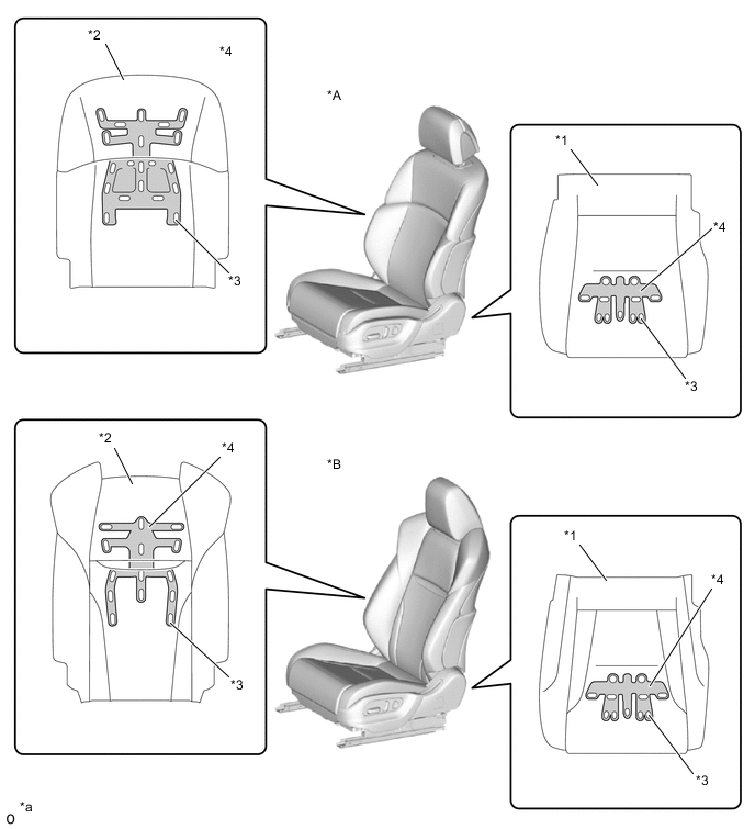
*A Normal Type Seat *B Sport Type Seat *1 Seat Cushion Pad *2 Seatback Pad *3 Hole in Surface of Pad *4 Groove *a The illustrations shown are examples only. - - Figure 2. Rear Seat
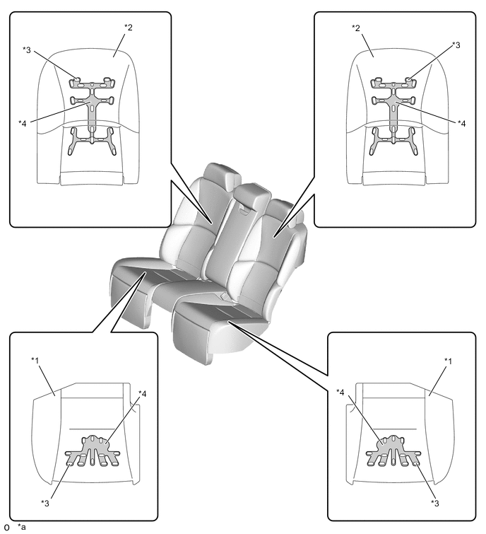
*1 Seat Cushion Pad *2 Seatback Pad *3 Hole in Surface of Pad *4 Groove *a The illustrations shown are examples only. - -
-
-
DIAGNOSIS
-
For details on the procedure required to enter the Service Menu screen, refer to the Repair Manual.
-