POWER SEAT CONTROL SYSTEM
-
FUNCTION OF MAIN COMPONENTS
Driver Seat Component Outline Position Control ECU Assembly
-
Receives signals from the main body ECU (multiplex network body ECU), etc. via CAN communication and determines operation conditions for the memory system.
-
Inputs signals from the position sensors for the seat adjusters in the driver seat and detects the slide, cushion length, reclining, front vertical, vertical lifter and headrest positions for the driver seat.
-
Receives seat memory switch operation signals from the front multiplex network door ECU LH via CAN communication and memorizes/recalls the driver seat position.
-
Sounds the built-in buzzer when the memorization operation completes or recall starts.
Main Body ECU (Multiplex Network Body ECU)
-
Inputs signals from the front door courtesy light switch assembly (LH) and sends driver door opening and closing signals to the position control ECU assembly via CAN communication.
-
Sends shift position signals from the ECM to the position control ECU assembly via CAN communication.
-
Inputs key ID signals and door lock/unlock signals and sends key ID and door lock/unlock signals to the position control ECU assembly via CAN communication.
-
Detects that the engine switch is on (IG) and sends signals to the position control ECU assembly via CAN communication.
-
Sends key code confirmation signals to the position control ECU assembly via CAN communication.
-
Inputs signals from the position sensor inside the tilt/telescopic motor and detects the tilt/telescopic position of the steering column.
-
Receives signals (memorization and recall commands) from the position control ECU assembly via CAN communication and memorizes or recalls the steering wheel position.
Front Door Courtesy Light Switch Assembly (LH) Detects the opening and closing of the driver door and sends signals to the main body ECU (multiplex network body ECU). Front Power Seat Switch LH Sends signals, which indicate the operation time of each seat adjuster switch of the driver seat, to the position control ECU assembly. Seat Memory Switch LH Outputs [Set Memory], [1], [2] or [3] button operation signals to the front multiplex network door ECU LH. Certification ECU (Smart Key ECU Assembly) Sends smart memory call recall command signals to the position control ECU assembly via CAN communication. Front Multiplex Network Door ECU LH
-
Inputs signals from each position sensor inside the outer rear view mirror and detects the mirror surface position of the outer rear view mirror.
-
Receives signals (memorize/recall commands) from the No.2 position control ECU assembly via CAN communication and memorizes/recalls the mirror surface position of the outer rear view mirror.
-
Sends operation signals from the seat memory switch LH to the position control ECU assembly via CAN communication.
Headup Display (Meter Mirror Sub-assembly)*
-
Meter Mirror ECU
Receives signals from ECUs and switches and projects various types of vehicle information onto the windshield glass. ECM Sends shift position signals to the main body ECU (multiplex network body ECU) via CAN communication. DLC3 The DTCs of malfunctioning parts can be read by connecting a diagnostic tool. *: Models with headup display
-
-
Passenger Seat Component Outline No.2 Position Control ECU Assembly
-
Inputs signals from the position sensors for the seat adjusters in the front passenger seat and detects the slide, reclining, lifter, headrest and support bladder positions for the front passenger seat.
Position Control ECU Assembly RH Sends ottoman position data to the No.2 position control ECU assembly via CAN communication. Main Body ECU (Multiplex Network Body ECU)
-
Inputs signals from the front door courtesy light switch assembly (RH) and sends front passenger door opening and closing signals to the No.2 position control ECU assembly via CAN communication.
-
Sends shift position signals from the ECM to the No.2 position control ECU assembly via CAN communication.
-
Detects that the engine switch is on (IG) and sends signals to the No.2 position control ECU assembly via CAN communication.
Front Door Courtesy Light Switch Assembly (RH) Detects the opening and closing of the front passenger door and sends signals to the main body ECU (multiplex network body ECU). Seat Memory Switch RH Outputs [Set Memory], [1], [2] or [3] button operation signals to the front multiplex network door ECU RH. Front Multiplex Network Door ECU RH Sends operation signals from the seat memory switch RH to the No.2 position control ECU assembly via CAN communication. ECM Sends shift position signals to the main body ECU (multiplex network body ECU) via CAN communication. -
-
OPERATION
-
Driving Position Memorization Operation
-
When memorization operation conditions are met, the main body ECU (multiplex network body ECU) sends memorize commands to the position control ECU assembly, multiplex tilt and telescopic ECU and front multiplex network door ECU LH. When the position control ECU assembly, multiplex tilt and telescopic ECU and front multiplex network door ECU LH receive these commands, they memorize the current seat position, steering wheel position, outer rear view mirror surface position and headup display (meter mirror sub-assembly) display position*.
-
*: Models with headup display
-
-
When driving position memorization is complete, a buzzer sounds for approximately 0.5 seconds.
-
-
Driving Position Recall Operation
-
When driving position recall operation conditions or key OFF recall operation conditions are met and a start recall command signal is received from the main body ECU (multiplex network body ECU), the position control ECU assembly sounds a buzzer for approximately 0.1 seconds, and then drives the seat adjuster motors in the specific recall operation order that was programmed ahead of time, until the current recognized seat position matches the memorized seat position.
-
The main body ECU (multiplex network body ECU) sends start recall command signals to the front multiplex network door ECU LH. When the front multiplex network door ECU LH receives start recall command signals, it drives the motors in the specific recall operation order that was programmed ahead of time, until the current recognized mirror surface position matches the memorized mirror surface position.
-
When it enters the recall operation step for the steering position, the main body ECU (multiplex network body ECU) sends start recall command signals to the multiplex tilt and telescopic ECU. When the main body ECU recognizes that the recall operation for the steering wheel position is complete based on communication with the multiplex tilt and telescopic ECU, it sends a signal to the position control ECU assembly to start driving the seat adjuster motor that is next in the sequence.
-
The main body ECU (multiplex network body ECU) sends start recall command signals to the headup display (meter mirror sub-assembly). When the headup display (meter mirror sub-assembly) receives a start recall command signal, the main body ECU drives the motors in the specific recall operation order that was programmed ahead of time, until the current recognized display position matches the memorized display position.*
-
*: Models with headup display
-
-
If the [1], [2] or [3] button on the seat memory switch is pressed with the engine switch on (IG) and the shift position in P, the driving position memorized by the system is recalled in the following order.
Driving Position Recall Operation Order Order Recall Operation Parts Seat/Steering Headrest Lumbar Support/Back Pelvis Support Outer Rear View Mirror Headup Display*1
(1) Slide Backward+Cushion Length Adjustment Headrest Downward→Headrest Front/Back - Mirror Position Display Position*2
(2) Reclining Backward (3) Steering Position (4) Reclining Forward (5) Slide Forward+Cushion Length Adjustment Lumbar Support Front/Back, Up/Down→Back Pelvis Support→Cushion Pelvis Support→Shoulder Support, Back Side Support→Cushion Side Support (Starts operating after reclining operation completes) (6) Lifter Headrest Up (Operates simultaneously with front vertical) (7) Front Vertical Tech Tips
*1: Models with headup display
*2: The headup display (meter mirror sub-assembly) moves only in the vertical direction.
-
-
Driving Position Key OFF Recall Function
-
Even if the engine switch is not turned on (IG), if the [1], [2] or [3] button on the seat memory switch LH is pressed within approximately 180 seconds from the moment the driver door was opened or within approximately 60 seconds from the moment the driver door was closed, the driver seat position is recalled in the same order as the driving position recall function. In this case, the steering wheel position is not recalled unless the engine switch is turned on (IG) before the driver seat position recall is complete.
-
If the engine switch is turned on (IG) during key OFF recall operation of the driver seat position, the step within the current operation sequence will be completed, the order will be determined with step (3) added, and then the steering wheel position will be recalled.
-
If the engine switch is turned on (IG) when recalling step (6) or (7), step (3) will be recalled immediately.
-
-
Memory Call Registration Operation
-
For electrical keys, if the user pushes the number of the seat memory switch LH to register while holding the key when memory call operation conditions are met, the memorized driving position is recalled. After recall, the user then presses the lock or unlock button on the door control switch while pressing the number of the seat memory switch LH again.
-
For card keys, the user presses the lock or unlock button on the driver door manual lock switch with the [1], [2] or [3] button on the seat memory switch LH pressed.
-
When the above operation is performed, the main body ECU (multiplex network body ECU) assigns the seat memory switch LH number and key ID, completing memory call registration.
-
When memory call registration is complete, a buzzer sounds for approximately 0.5 seconds.
-
-
Memory Call Deregistration Operation
-
If the user is holding the electrical key when memory call operation conditions are met and then presses the lock or unlock button on the key with the [Set Memory] button on the seat memory switch LH pressed, or presses the lock or unlock button on the driver door manual lock switch, the position control ECU assembly continues to receive seat memory switch LH [Set Memory] signals from the front multiplex network door ECU LH as it receives key ID signals from the certification ECU.
-
For card keys, the user presses the lock or unlock button on the driver door manual lock switch with the [Set Memory] button on the seat memory switch LH pressed.
-
When the position control ECU assembly receives seat memory switch LH [Set Memory] signals and key ID signals, it deregisters the memory call for the electrical key that was operated.
-
When memory call deregistration is complete, a buzzer sounds twice at approximately 0.1 second intervals. Memory call deregistration will not complete successfully if there are 2 or more electrical keys or card keys in the cabin. In this case, the buzzer sounds for approximately 3 seconds.
-
-
Memory Call Recall Operation
-
If the door is unlocked using the smart door unlock function (or the unlock switch on the electrical key) when memory call operation conditions are met, the main body ECU (multiplex network body ECU) receives key ID signals and door unlock signals.
-
If the driver door is opened in this state, the main body ECU (multiplex network body ECU) starts the memory call recall operation via CAN communication.
-
When memory call recall starts, a buzzer sounds for approximately 0.1 seconds.
-
This supports the customization function via diagnostic tool or operation of the multi display screen, and it is possible to change the memory call-linked door setting from "driver door" to "all doors" (driver door and front passenger door). Refer to the Repair Manual for details on the customization function.
-
-
Seat Position Memorization Operation
-
When memorization operation conditions are met, the main body ECU (multiplex network body ECU) sends memorize commands to the No.2 position control ECU assembly. After receiving this, the No.2 position control ECU assembly memorizes the current seat position.
-
When front passenger seat position memorization is complete, a buzzer sounds for approximately 0.5 seconds.
-
-
Seat Position Recall Operation
-
When driving position recall operation conditions or key OFF recall operation conditions are met and a start recall command signal is received from the main body ECU (multiplex network body ECU), the No.2 position control ECU assembly sounds a buzzer for approximately 0.1 seconds, and then drives the seat adjuster motors in the specific recall operation order that was programmed ahead of time, until the current recognized seat position matches the memorized seat position.
-
-
-
FUNCTION
-
Driving Position Memorization Function
-
When the [Set Memory] and [1], [2] or [3] button on the rear multi operation panel are pressed*2 simultaneously, or the [1], [2] or [3] button is pressed*2 within approximately 3 seconds after pressing the [Set Memory] button with the engine switch on (IG)*1, the driving position (driver seat slide, reclining, front vertical, lifter, steering column tilt and telescopic and outer rear view mirror surface positions) when the switch was pressed is memorized by the system.
Tech Tips
*1: If the front power seat switch LH, tilt and telescopic switch or door mirror switch is being operated, or the headup display (meter mirror sub-assembly) (for models with a headup display (meter mirror sub-assembly)) position setting is being operated, the position of the part being operated is not be memorized. The positions of parts not being operated by switch are memorized and the buzzer sounds. Memorization operations are disabled during driving position recall operation. In this case, either stop operating each switch, or operate after the recall operation is complete.
*2: Memorization operations are disabled if several of the [1], [2] and [3] buttons on the rear multi operation panel are pressed simultaneously. In this case, release the switches and then try again.
-
-
Driving Position Recall Function
-
If the [1], [2] or [3] button on the seat memory switch LH is pressed with the engine switch on (IG) and the shift position in P, the driving position memorized by the system is recalled in the following order.
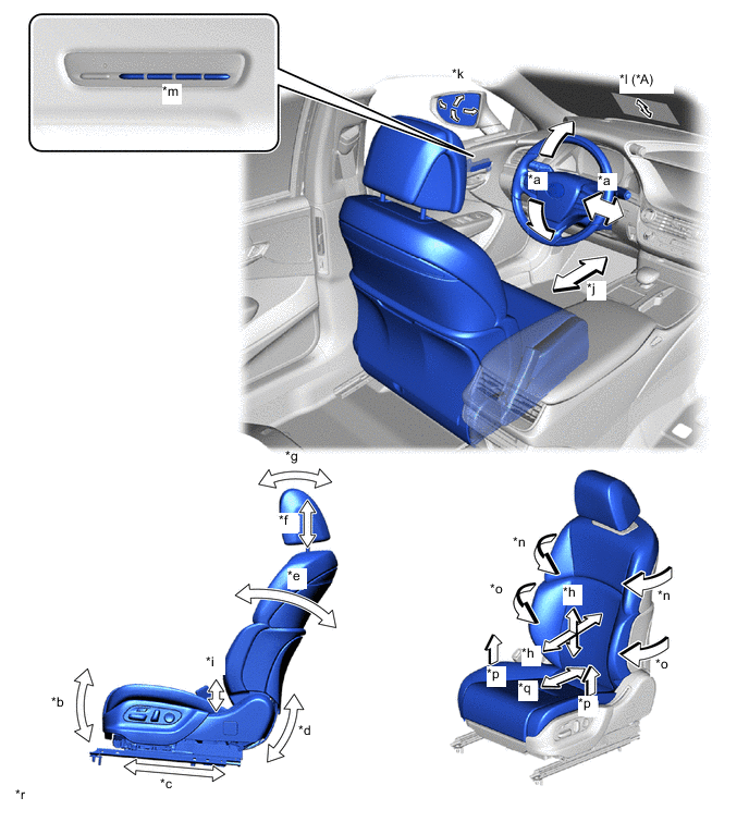
*A Models with head up display - - *a Steering Tilt/Telescopic Position *b Front Vertical Position *c Seat Slide Position *d Lifter Position *e Reclining Position *f Headrest Up/Down Position *g Headrest Front/Back Position *h Lumbar Support Position *i Hip Support Position *j Cushion Length Position *k Outer Rear View Mirror Position *l Head up Display Position *m Seat Memory Switch LH *n Shoulder Support Position *o Back Side Support Position *p Cushion Side Support Position *q Back Pelvis Support Position *r The illustrations shown are examples only.
-
-
Driving Position Key OFF Recall Function
-
Even if the engine switch is not turned on (IG), if the [1], [2] or [3] button on the seat memory switch LH is pressed within approximately 180 seconds from the moment the driver door was opened or within approximately 60 seconds from the moment the driver door was closed, the driver seat position is recalled in the same order as the driving position recall function. In this case, the steering wheel position is not recalled unless the engine switch is turned on (IG) before the driver seat position recall is complete.
-
If the engine switch is turned on (IG) during key OFF recall operation of the driver seat position, the step within the current operation sequence will be completed, the order will be determined with step (3) added, and then the steering wheel position will be recalled.
-
If the engine switch is turned on (IG) when recalling step (6) or (7), step (3) will be recalled immediately.
-
-
Pneumatic Support Mechanism
-
When the power seat switch or a pneumatic support switch on the multi display is operated, the pneumatic control ECU drives the lumbar support pump sub-assembly, air is sent from the applicable valve to the bladder, and the bladder expands.
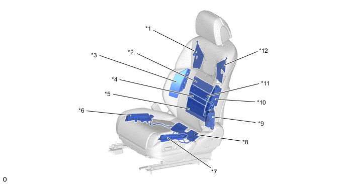
*1 Shoulder Bladder RH *2 Lumbar Bladder (Upper) *3 Front No. 2 Seatback Support *4 Lumbar Bladder (Lower) *5 Seatback Pelvic Bladder *6 RH Seat Support Inner *7 RH Seat Support Outer *8 Front Seat Adjuster LH *9 Lumbar Support Pump Sub-assembly *10 Front No. 3 Seatback Support *11 Lumbar Bladder (Center) *12 Shoulder Bladder LH
-
-
Sliding-linked Adjustment Headrest
-
Passenger height is determined from the slide operation amount, and the height of the headrest is automatically adjusted.
-
The slide position and headrest height are detected by the No.2 position control ECU Assembly , based on signals sent from position sensors installed in each adjuster.
-
When operation start conditions are met, the difference between the headrest position for the current slide position of the seat and the target headrest height for the slide position of the seat is calculated, and the headrest adjuster is operated to reach the target headrest height.
-
-
Electric Up/Down Adjustment Type Headrest
-
The motor and worm gear attached to the rear of the housing rotate when the headrest switch is operated. This rotation causes the pinion gear on the front of the housing to rotate, which then causes the sector gear housing interlocked with the pinion gear to rotate.
-
The sector gear housing is fixed in place with a pin (fulcrum A), and rotates around fulcrum A. The move attached to the sector gear housing moves up and down along the housing as the sector gear housing rotates.
-
Headrest stays are attached to either end of the move to move the headrest up and down along with the move.
-
-
Seat Position Memorization Function
-
When the engine switch is on (IG)*1 and the [1], [2] or [3] button is pressed*2 with the [Set Memory] button on the seat memory switch RH turned on, or the [1], [2] or [3] button is pressed*2 within 3 seconds of turning the [Set Memory] button on the seat memory switch RH on, the front passenger seat position (seat slide, reclining, front vertical, lifter, headrest (up/down and front/back) and cushion length variable mechanism using the electric adjuster, and via the lumbar support (up/down and front/back), back pelvis support, shoulder support, backside support, hip support and cushion side support using the pneumatic system) when the switch was pressed is memorized by the system.
Tech Tips
*1: If the front power seat switch LH is being operated, the seat position is not memorized. Memorization operations are disabled during front passenger seat position recall operation. In this case, either stop operating each switch, or operate after the recall operation is complete.
*2: Memorization operations are disabled if several of the [Set Memory], [1], [2] and [3] buttons on the seat memory switch RH are pressed simultaneously. In this case, release the switches and then try again.
-
-
Seat Position Recall Function
-
If the [1], [2] or [3] button on the seat memory switch RH is pressed with the engine switch on (IG) and the shift position in P (or the shift position in N at a vehicle speed of 3 km/h or lower), the front passenger seat position memorized by the system is recalled in the following order.
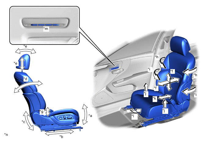
*a Front Vertical Position *b Seat Slide Position *c Lifter Position *d Reclining Position *e Headrest Position *f Lumbar Support Position *g Hip Support Position *h Shoulder Support Position *i Back Side Support Position *j Cushion Side Support Position *k Back Pelvis Support Position *l Cushion Length Position *m Seat Memory Switch RH *n The illustrations shown are examples only.
-
-
Seat Position Key OFF Recall Function
-
Even if the engine switch is not turned on (IG), if the [1], [2] or [3] button on the seat memory switch LH is pressed within approximately 180 seconds from the moment the front passenger door was opened, the front passenger seat position is recalled in the same order as the front passenger seat position recall function.
-
If the engine switch is turned on (IG) during key OFF recall operation of the front passenger seat position, that step will be completed.
-
-
-
DIAGNOSIS
-
The position control ECU assembly (front power seat switch) has a diagnosis function. It stores a record of any power seat control system malfunctions in its memory in the form of Diagnostic Trouble Codes (DTCs).
-