PARKING SUPPORT ALERT SYSTEM
-
FUNCTION OF MAIN COMPONENTS
Component Function Blind Spot Monitor Sensor LH Sounds the RCTA buzzer when a pedestrian detection signal is received from the television camera assembly. Blind Spot Monitor Sensor RH Sends pedestrian detection signals from the television camera assembly to the blind spot monitor sensor LH. Television Camera Assembly Detects pedestrians behind the vehicle and sends a pedestrian detection display signal to the parking assist ECU. RCTA Buzzer (Blind Spot Monitor Buzzer) Sounds an alarm to notify the driver when a pedestrian is detected behind the vehicle. Multi-display Displays detection information to notify the driver when a pedestrian is detected behind the vehicle. Combination Meter Assembly
-
RCD OFF Indicator
-
Multi-information Display
-
Master Warning Indicator
-
Sends a RCD on/off signal to the television camera assembly.
-
Illuminates the RCD OFF indicator when RCD is off.
-
Illuminates the master warning indicator and displays a warning message on the multi-function display to warn the driver when a malfunction is detected in the television camera assembly, or when it is determined that the television camera assembly cannot be controlled.
-
Sends customization information to the television camera assembly.
Parking Assist ECU Receives pedestrian detection signals from the television camera assembly and outputs a video signal to the multi-display. Steering Sensor Sends a steering angle signal to the television camera assembly. ECM Sends a shift position signal to the television camera assembly. Skid Control ECU Sends a vehicle speed signal to the television camera assembly. Central Gateway ECU (Network Gateway ECU) Relays the signal between the CAN communication buses. DLC3
-
The Global TechStream (GTS) can be connected to read the Diagnostic Trouble Codes (DTCs) of malfunctions.
-
The Global TechStream (GTS) can be connected to change settings as desired by the user.
-
-
OPERATING CONDITION
-
RCD operates when all of the following conditions are established.
-
Engine switch is on (IG).
-
RCD is on.
-
The shift position is R.
-
-
-
SYSTEM CONTROL
-
If a pedestrian is in the area behind the vehicle or if the television camera assembly detects that a pedestrian is approaching the vehicle from behind, the system urges caution from the driver by sounding the RCTA buzzer and displaying information on the multi-display, as shown below.
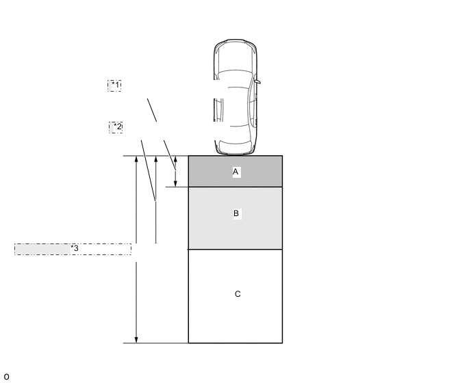
*1 Approximately 1 m (3.3 ft.) *2 Approximately 3 m (9.8 ft.) *3 Approximately 6 m (16.4 ft.) Area Warning Buzzer Icon Display on Multi-display A Sounds repeatedly. Blinks 3 times then stays illuminated. B When own vehicle is stopped: Sounds 3 times. Blinks 3 times then stays illuminated. When own vehicle is moving: Sounds repeatedly. C If own vehicle and pedestrian approach area A within a certain amount of time: Sounds repeatedly. If own vehicle and pedestrian approach area A within a certain amount of time: Sounds 3 times, then stays illuminated. -
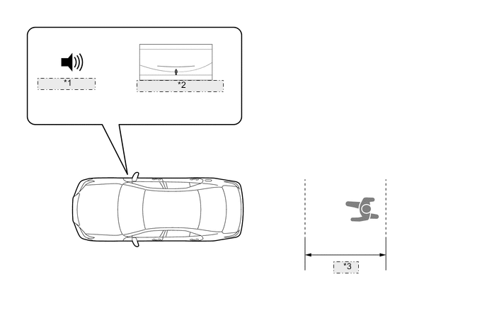
If a pedestrian is detected in warning area A, a repeating alarm sounds, and then the icon blinks 3 times and stays illuminated to warn the driver.
*1 Sounds repeatedly *2 Blinks 3 Times then Stays Illuminated. *3 Area A -
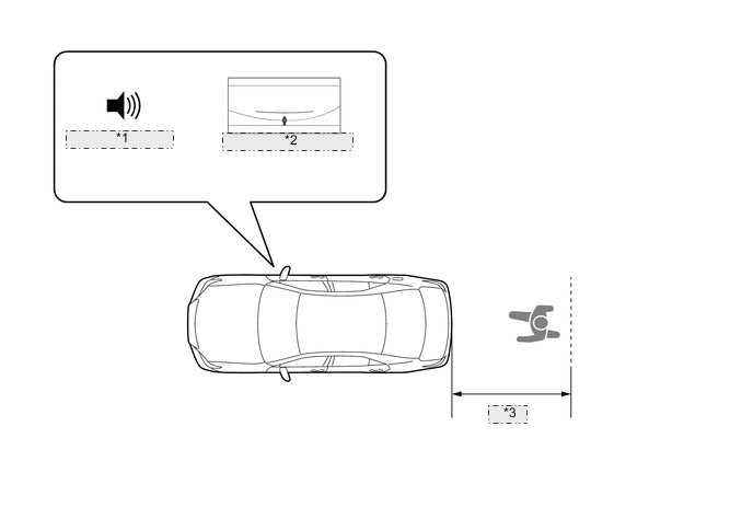
If a pedestrian is detected in warning area B and the driver's own vehicle is stopped, the buzzer sounds 3 times and then the icon blinks 3 times and stays illuminated to warn the driver.
Figure 1. Own Vehicle Stopped
*1 Sounds 3 Times *2 Blinks 3 Times then Stays Illuminated. *3 Area B Figure 2. Own Vehicle Moving
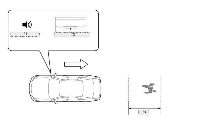
*1 Sounds repeatedly *2 Blinks 3 Times then Stays Illuminated *3 Area B -
If a pedestrian is detected in warning area C or if the driver's own vehicle and the pedestrian approach area A within a certain amount of time, the buzzer sounds repeatedly, and then the icon blinks 3 times and stays illuminated to warn the driver.
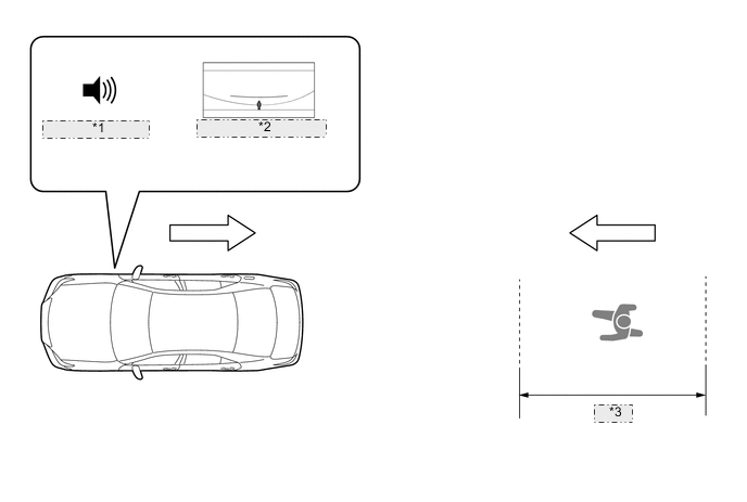
*1 Sounds repeatedly *2 Blinks 3 Times then Stays Illuminated. *3 Area C
-
-
FUNCTION
-
RCD Operation
-
The combination meter assembly customization setting can be used to turn RCD on and off.
-
A RCD OFF indicator is located in the combination meter assembly to make it possible to check whether RCD is on or off. When the RCD is off, the indicator illuminates to indicate the operation status.
-
The combination meter assembly customization setting can be used to change the volume of the buzzer.
-
-
Buzzer Sound Temporary Mute Function
-
When the buzzer is sounding, the warning buzzer can be temporarily muted by operating the steering pad switch assembly.
Tech Tips
Then, If the shift position is changed to R, the temporary mute function is automatically canceled.
-
-
Customization Function
-
Settings of some functions can be changed as desired by the user. Refer to the Repair Manual for details.
-
-
-
DIAGNOSIS
-
In order to make system inspections easier to perform, a diagnosis function is used in consideration of serviceability. The DTCs of malfunctioning parts can be read by connecting the Global TechStream (GTS). Refer to the Repair Manual for details.
-