PARKING SUPPORT ALERT SYSTEM
-
FUNCTION OF MAIN COMPONENTS
Component Function Blind Spot Monitor Sensor RH/LH
-
Projects radar waves and detects the presence of other vehicles, the vehicle-to-vehicle distance and the relative vehicle speed.
-
Determines if other vehicles are around, then blinks the outer rear view mirror indicator light and sounds the RCTA buzzer.
-
Sends a vehicle detection signal to the parking assist ECU.
Outer Rear View Mirror Assembly RH/LH
-
Outer Rear View Mirror Indicator Light
Blinks the outer rear view mirror indicator lights on both sides to notify the driver when it is detected that a vehicle within the detection range is approaching from the rear. RCTA Buzzer (Blind Spot Monitor Buzzer) Sounds an alarm to notify the driver when it is detected that a vehicle within the detection range is approaching from the rear. Multi-display Displays detection information to notify the driver when it is detected that a vehicle within the detection range is approaching from the rear. Combination Meter Assembly
-
RCTA OFF Indicator
-
Multi-information Display
-
Master Warning Indicator
-
Sends the RCTA on/off signal to the blind spot monitor sensor RH.
-
When the RCTA is off, illuminates the RCTA OFF indicator.
-
Illuminates the master warning indicator and displays a warning message to alert the driver when a blind spot monitor sensor malfunction is detected or when it is determined that the blind spot monitor sensor cannot be controlled.
-
Sends customization information to the blind spot monitor sensor RH.
Parking Assist ECU*1 Receives signals from the blind spot monitor sensor RH and outputs a video signal to the multi-display. Television Camera Assembly*2 Steering Angle Sensor Sends a steering angle signal to the blind spot monitor sensor RH. Yawrate Sensor Sends a yaw rate signal to the blind spot monitor sensor RH. ECM Sends a shift position signal to the blind spot monitor sensor RH. Skid Control ECU Assembly*3 Sends a vehicle speed signal to the blind spot monitor sensor RH Skid Control ECU*4 Central Gateway ECU (Network Gateway ECU) Relays the signal between the CAN communication buses. DLC3
-
The Global TechStream (GTS) can be connected to read the Diagnostic Trouble Codes (DTCs) of malfunctions.
-
The Global TechStream (GTS) can be connected to change settings as desired by the user.
*1: Models with panoramic view monitor system
*2: Models without panoramic view monitor system
*3: Models with electronically controlled brake system
*4: Models with vacuum brake booster
-
-
OPERATING CONDITION
-
The RCTA operates when all of the following conditions are met.
-
The RCTA is on.
-
The shift position is R.
-
The vehicle speed is approximately 8 km/h (5 mph) or less.
-
The speed of the other vehicle is approximately from 8 km/h (5 mph) to 28 km/h (18 mph).
-
ECT* is 2.5 seconds or less.
Tech Tips
*: Estimated Crossing Time
-
-
-
SYSTEM CONTROL
-
The RCTA can detect vehicles in the following detection range.
-
The blind spot monitor sensor LH and RH detect and continuously calculate the relative speed and position of the detected vehicle, then calculate the ECT when there is the possibility of the other vehicle crossing the path of the driver's own vehicle. A warning is generated if the ECT is 2.5 seconds or less.
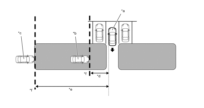
*a Own Vehicle *b Other Vehicle (Approximately 8 km/h (5 mph)) *c Other Vehicle (Approximately 28 km/h (18 mph)) *d Approximately 5.5 m (18.0 ft.) *e Approximately 20 m (66 ft.) *f Vehicle Detection Line 
Detection Area - -
-
-
Detects other vehicles approaching the driver's own vehicle from the rear.
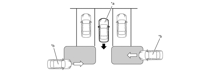
*a Own Vehicle *b Other Vehicle 
Detection Area - - -
When operating conditions match, the RCTA blinks the outer rear view mirror indicator lights on the left and right side of the vehicle, and sounds the RCTA buzzer. This is done to notify the driver that a vehicle is approaching from the left rear or right rear and urges him or her to confirm that conditions are safe.
-
-
FUNCTION
-
RCTA Operation
-
The combination meter assembly customization setting can be used to turn the RCTA on and off.
-
The RCTA OFF indicator is located in the combination meter assembly to make it possible to check whether the RCTA is on or off. When the RCTA is off, the indicator illuminates to indicate the operation status.
-
The combination meter assembly customization setting can be used to change the volume of the RCTA buzzer.
-
-
RCTA Buzzer Sound Temporary Mute Function
-
When the RCTA buzzer is sounding, the warning buzzer can be temporarily muted by using the steering pad switch assembly to operate the multi-information display.
Tech Tips
Then, if the shift position is changed to R, the temporary mute function is automatically canceled.
-
-
Customization Function
-
Settings of some functions can be changed as desired by the user. Refer to the Repair Manual for details.
-
-
-
DIAGNOSIS
-
In order to make system inspections easier to perform, a diagnosis function is used in consideration of serviceability. The DTCs of malfunctioning parts can be read by connecting the Global TechStream (GTS). Refer to the Repair Manual for details.
-