PARKING ASSIST MONITOR SYSTEM
-
FUNCTION OF MAIN COMPONENTS
Component Function Television Camera Assembly
-
Captures images of the area behind the vehicle.
-
The parking assist guide lines that are calculated based on signals from the steering sensor are superimposed on the captured image. Then, the image is sent to the multi-display as video signals.
-
When the luggage compartment door is open, superimposing of parking assist guide lines is canceled and only the captured image is sent as video signals.
Multi-display Receives visual signals composed of the area behind the vehicle with parking assist guide lines overlaid from the television camera assembly, and displays them. Radio Receiver Assembly Sends signals indicating a mode change in parking guide line display functions to the television camera assembly. Steering Sensor Detects the direction and angle of the steering wheel and sends the resulting signals to the television camera assembly. ECM Sends an R shift position signal to the television camera assembly. Main Body ECU (Multiplex Network Body ECU) Sends the luggage compartment door condition signal to the television camera assembly. Clearance Warning ECU Assembly Sends a Lexus parking assist-sensor information signal to the television camera assembly. Blind Spot Monitor Sensor RH*1 Sends a RCTA information signal to the television camera assembly. Remote Touch (Remote Operation Controller Assembly) Sends operation signals to the radio receiver assembly. FR Steering Control ECU*2 Sends the VGRS signal to the television camera assembly. No. 3 Semiconductor Power Integration ECU Sends the shift position R signal to the multi-display. Central Gateway ECU (Network Gateway ECU) Relays the signal between the CAN communication buses. DLC3 The Global TechStream (GTS) can be connected to read the Diagnostic Trouble Codes (DTCs) of malfunctions. *1: Models with blind spot monitor system
*2: Models with VGRS system
-
-
OPERATING CONDITION
-
The parking assist monitor system operates when both of the following conditions are met:
-
The engine switch is on (IG).
-
The shift position is R.
-
-
-
SYSTEM CONTROL
-
The television camera assembly combines guide lines and an image to the rear of the vehicle captured and outputs a video signal to the multi-display.
-
2 types of screen modes are provided: rear view mode and wide rear view mode. Rear view mode helps the safety confirmation when parking. Wide rear view mode helps the safety confirmation in left and right directions during start-off using the wide visible area.
-
Estimated course line display mode, parking assist guide line display mode and distance guide line display mode are provided for guide line display mode.
Guide Line Display Mode List Guide Line Display Mode Outline Estimated Course Line Display Mode Estimated course lines are displayed which move in accordance with the operation of the steering wheel. Parking Assist Guide Line Display Mode The steering wheel return points (parking assist guide line) are displayed. Distance Guide Line Display Mode Distance guide lines only are displayed. Figure 1. Rear View Mode
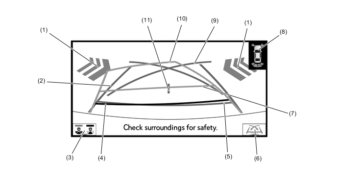
Tech Tips
The illustration shown is an example only. The illustration may differ from the actual vehicle screen.
Figure 2. Wide Rear View Mode
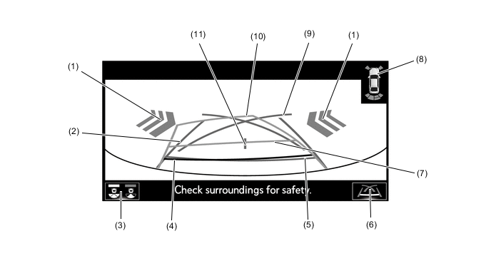
Tech Tips
The illustration shown is an example only. The illustration may differ from the actual vehicle screen.
Rear View Mode/Wide Rear View Mode Screen Display Contents List No. Item Description (1) RCTA Icon* If a vehicle in the rear side direction detected when the RCTA is activated, the RCTA icon is displayed. (2) Vehicle Width Guide Line (Blue) Indicates the estimated vehicle width. (3) Display Mode Switching Button The rear view mode and the wide rear view mode are switched. (4) Distance Guide Line (Red) Moves together with estimated course lines in sync with the steering wheel. The center of the line indicates a position on the ground approximately 0.5 m (1.6 ft.) behind the rear bumper. (5) Distance Guide Line (Blue) Indicates a position on the ground approximately 0.5 m (1.6 ft.) behind the rear bumper. (6) Guide Line Switching Button Select to switch the guide line mode. (7) Distance Guide Line (Yellow) Moves together with estimated course lines in sync with the steering wheel. The center of the line indicates a position on the ground approximately 1.0 m (3.3 ft.) behind the rear bumper. (8) Lexus parking assist-sensor Icon If an obstacle is detected when the Lexus parking assist-sensor is activated, the approximate distance between the vehicle and the obstacle is displayed. (9) Parking Assist Guide Line (Blue) Indicates the path the vehicle will follow if the driver turns the steering wheel fully. (10) Estimated Course Line (Yellow) Moves in sync with the steering wheel to indicate the estimated reverse course of the vehicle. (11) Vehicle Center Guide Line (Blue) Indicates the estimated position on the ground of the center of the vehicle. *: Models with blind spot monitor system
-
Estimated Course Line Display Mode
-
The estimated course lines inform the driver of the steering angle when driving in reverse. By driving the vehicle in reverse while steering to match the estimated course lines with the parking space boundary line, the vehicle can be guided into the parking space.
-
The vehicle width guide lines can be used to determine whether the vehicle is parked straight in the parking space by confirming whether the parking space boundary line and vehicle width extension lines are crossed or parallel.
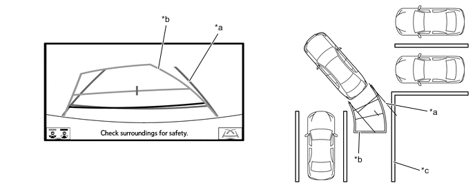
*a Vehicle Width Guide Line *b Estimated Course Line *c Painted Line of the Parking Space - -
-
-
Parking Assist Guide Line Display Mode
-
The parking assist guide lines inform the driver of a part outside of the estimated course lines when the steering wheel is fully turned while driving in reverse. By driving the vehicle in reverse to the desired parking position that matches the parking guide lines with the parking space boundary line, sides of the road, etc., the vehicle can be guided to an appropriate position to start turning the steering wheel.
Figure 3. Perpendicular Parking
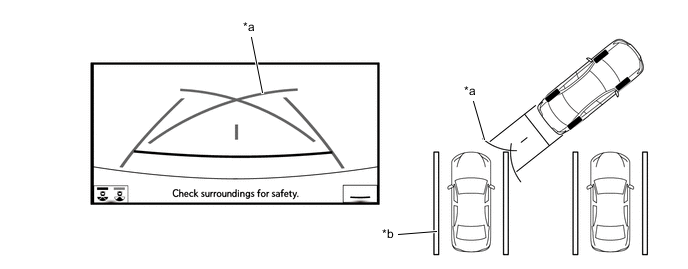
*a Parking Assist Guide Line *b Painted Line of the Parking Space Figure 4. Parallel Parking
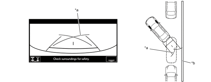
*a Parking Assist Guide Line *b Shoulder and Parking Space Lines, etc.
-
-
-
-
DIAGNOSIS
-
The rear television camera is equipped with a diagnosis function. For details, refer to the Repair Manual.
-