LEXUS DYNAMIC HANDLING
-
FUNCTION OF MAIN COMPONENTS
Component Function Steering Sensor Detects the rotational direction and angle of the steering wheel. Yawrate Sensor Detects the angular velocity and lateral and longitudinal acceleration of the vehicle. Steering Actuator Assembly Rotation Angle Sensor Detects the rotation angle of the motor. Motor Rotates upon receiving the operation signals from the front steering control ECU, operating the reduction mechanism. Reduction Mechanism
-
Uses a strain wave gear type reduction mechanism to reduce the rotation of the motor to the 1:50 ratio.
-
Operates in accordance with the rotation of the motor, creating the VGRS operation angle between the input and output shafts of the steering actuator assembly.
Lock Solenoid Locks the motor in order to prevent operation of the steering actuator assembly when a system malfunction is detected or the engine switch (push start switch) is turned off. Rear Steering Link Assembly Rotation Angle Sensor Detects the rotation angle of the motor. Motor Rotates upon receiving the operation signal from the rear steering control ECU, steering the rear wheels. Rear Steering Sensor Detects the stroke amount of the rear steering link assembly. Front Steering Control ECU
-
Calculates the target front wheel turning angle based on the signals of the steered angle of the steering wheel and vehicle speed and drives the motor of the steering actuator assembly.
-
Calculates the target rear wheel turning angle based on the signals of the steered angle of the steering wheel and vehicle speed and sends the control signal to the rear steering control ECU.
Rear Steering Control ECU Drives the motor of the rear steering link assembly in accordance with the target rear wheel turning angle signal from the front steering control ECU. Power Steering ECU Sends steering cooperation information to the front steering control ECU. Skid Control ECU Sends the vehicle speed signal and cooperative steering control amount signal to the front steering control ECU. ECM Sends the drive mode select signal to the front steering control ECU. Driving Support ECU Assembly* Sends VGRS operation request signals to the front steering control ECU. Combination Meter Assembly Multi-information Display Displays a warning message to inform the driver of a malfunction in the system. Master Warning Light Illuminates to inform the driver of a malfunction in the system. Buzzer Sounds to inform the driver of a malfunction in the system. *: Models with pre-collision system
-
-
SYSTEM CONTROL
-
Target Vehicle Characteristics in Accordance with Vehicle Speed
-
In the LDH system, target vehicle characteristics are calculated in accordance with the vehicle speed to allow the turning angles of the front and rear wheels to be steered to the optimum angle in response to the steered angle of the steering wheel.
-
The LDH system controls the turning angles of the front and rear wheels in accordance with the steered angle of the steering wheel and vehicle speed, meeting the requirements of the target vehicle characteristics.
Figure 1. Target Vehicle Characteristics (Slip Angle)
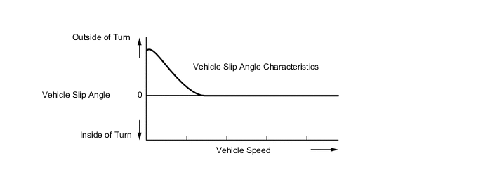
Figure 2. Target Vehicle Characteristics (Yaw Rate)
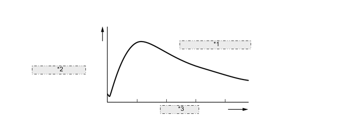
*1 Yaw Rate Characteristics *2 Vehicle Spin Speed *3 Vehicle Speed Figure 3. Control Image (Front Wheel)
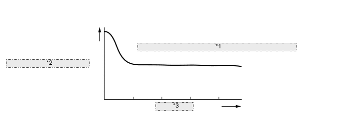
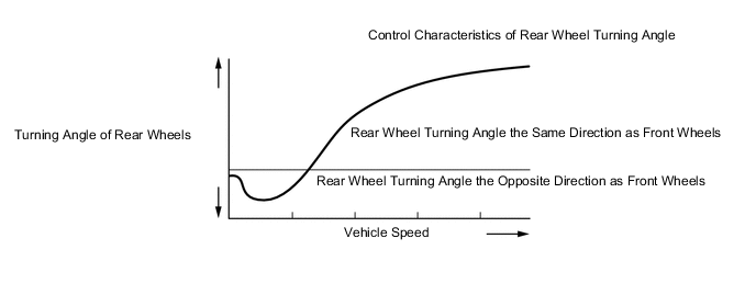
*1 Control Characteristics of Front Wheel Turning Angle *2 Turning Angle of Front Wheels *3 Vehicle Speed Figure 4. Control Image (Rear Wheel)
-
Control in Medium Speed Range (Improvement on Steering Response)
-
In the medium speed range, target vehicle characteristics are set at a level which ensures superior turning performance. With this, in areas where a lot of turning operations are required, such as in a city or on a mountain road, a light steering feel that is appropriate for the driver is achieved.
-
-
Control in High-speed Range (Improvement on Comfort and Stability)
-
While turning at high speed in a conventional front wheel steered vehicle, the rear wheels have a slight tendency to travel towards the outside of the turn. Therefore, the longitudinal centerline of the vehicle points more towards the inside of the turn than the tangent of the turning circle. The higher the vehicle speed, the greater the effect.
-
In the high speed range, the target vehicle slip angle is set to approximately 0. This enables the rear wheels to react to changes in the steering wheel angle with almost zero delay achieving both a high level of stability and response appropriate to the driver's intentions.
-
-
-
Control in SPORT Mode
-
When SPORT S+ mode is selected by operating the drive mode select, the front steering control ECU changes the steering gear ratio characteristics for sporty driving, enhancing the vehicle steering response compared to that of Normal mode.
-
-
Cooperative Control with EPS
-
Upon receiving signals from the skid control ECU, the front steering control ECU controls the front and rear wheel turning angles.
-
Control during Brake Operation on Road Surface with Different Friction Coefficients
-
When breaking on a split friction road, the vehicle tends to deflect toward the high friction side due to the greater brake force. In this state, the system steers the front wheels toward the low friction side, canceling the moment generated in the vehicle turning direction.
-
By steering the rear wheels in a direction opposite to the front wheels, the vehicle lateral movement is controlled.
Figure 5. Control Image
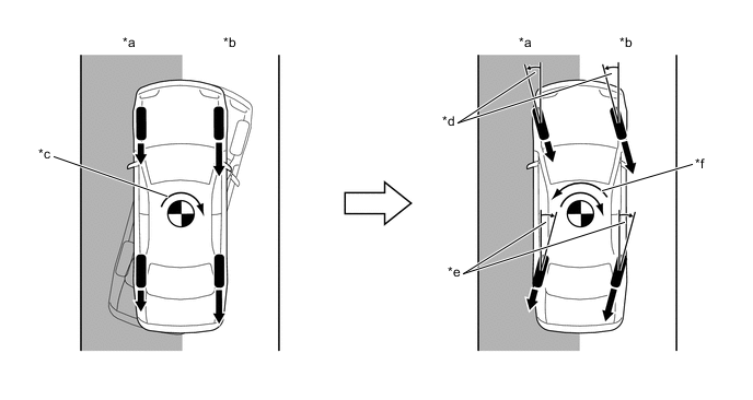
*a Low Friction Road *b High Friction Road *c Moment Generated due to Difference between Brake Force of Left and Right Wheels *d Front Wheel Steering Control *e Rear Wheel Steering Control *f Stabilizing Moment Generated due to Steering Control 
Brake Force - - -
Control during Acceleration on Road Surface with Different Friction Coefficients
-
When accelerating on a split friction road, the vehicle tends to deflect toward the low friction side due to the lower acceleration force. In this state, the system steers the front wheels toward the high friction side, canceling the moment generated in the vehicle turning direction.
-
By steering the rear wheels in a direction opposite to the front wheels, the vehicle lateral movement is controlled.
Figure 6. Control Image
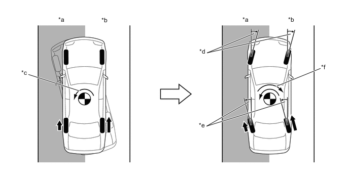
*a Low Friction Road *b High Friction Road *c Moment Generated due to Difference between Drive Force of Left and Right Wheels *d Front Wheel Steering Control *e Rear Wheel Steering Control *f Stabilizing Moment Generated due to Steering Control Drive Force - - Tech Tips
-
On models without an LDH system, the VDIM controls the vehicle to keep it moving straight.
-
On models with an LDH system, the vehicle stability is more improved, thus control can be maintained during heavy braking and acceleration.
-
-
Oversteer Control
-
If an oversteer tendency (rear wheel skid) is detected, normal brake and drive force control is performed in cooperation with the rear wheel steering control, stabilizing the vehicle maneuver.
-
In addition to normal brake and drive forces, the stabilizing moment generated by steering control enhances the vehicle stability without the feeling of excessive deceleration.
Figure 7. Control Image
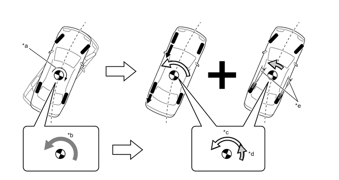
*a Oversteer Tendency (Rear Wheel Skid) *b Stabilizing Moment Required to Reduce Oversteer (Rear Wheel Skid) *c Stabilizing Moment due to Brake and Drive Force Control *d Stabilizing Moment due to Steering Control *e Rear Wheel Steering Control - - Brake Force - - -
Understeer Control
-
When an understeer tendency (front wheel skid) is detected, by controlling both brake force and drive force, the moment towards the vehicle turning direction is generated, reducing excessive understeer.
-
By changing the steering gear ratio of the VGRS system, excessive front wheel steering is reduced. Steering torque assist is provided in the opposite direction of the steering operation, encouraging the driver to make corrective steering operations.
-
Rear wheel steering control increases the moment in the turning direction to ensure sufficient turning performance.
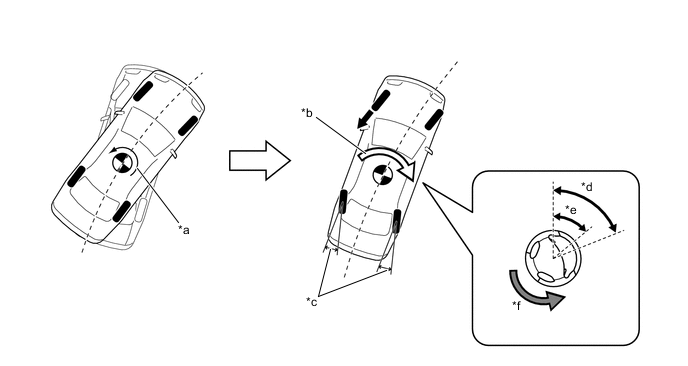
*a Understeer Tendency (Front Wheel Skid) *b Stabilizing Moment due to Brake and Drive Force Control *c Rear Wheel Steering Control *d Steered Angle of Driver Operation *e The VGRS alters the steering gear ratio to make the actual front wheel turning angle narrower than the steered angle of the driver operation. *f The EPS assists the steering torque in the direction opposite to the front wheel turning direction. Brake Force - -
-
-
-
-
FAIL-SAFE
-
If a malfunction is detected in the system, the system enters fail-safe mode. The system informs the driver of the malfunction by illuminating the master warning light, displaying a warning message on the multi-information display in the combination meter assembly in accordance with the system malfunction, and sounding the buzzer.
-
If the system enters fail-safe mode, power to the lock mechanism is cut off which engages the lock mechanism inside the steering actuator assembly to directly connect the housing to the output shaft in order to ensure normal steering operation. Additionally, the output power to the motor of the rear steering link assembly is cut off or gradually reduced, preventing rear wheel steering control from being performed.
-
-
DIAGNOSIS
-
The system stores Diagnostic Trouble Codes (DTCs) when a malfunction is detected. The DTCs can be accessed through the use of the Global TechStream (GTS). For details, refer to the Repair Manual.
-