BRAKE CONTROL SYSTEM(w/o Vacuum Brake Booster)
-
CONSTRUCTION
-
The brake booster pump assembly consists of an accumulator, pump and pump motor.
-
A plunger type pump is used. This pump is operated by the rotation of a camshaft driven by the pump motor, and supplies high-pressurized fluid to the accumulator.
-
High-pressure nitrogen gas is charged and sealed in the accumulator. The accumulator has been made more compact by using a metallic bellows-formed tube.
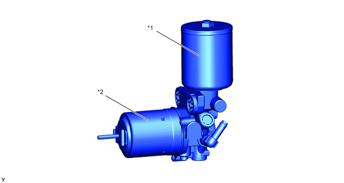
*1 Pump Motor *2 Accumulator
-
-
OPERATION
-
When the skid control ECU assembly detects drops in the accumulator hydraulic pressure according to the accumulator pressure sensor (PACC), it turns the No. 1 ABS MTR relay on to operate the pump motor. Also, when the skid control ECU assembly detects that the accumulator hydraulic pressure has dropped further, it illuminates the brake system warning light/red and sounds a buzzer to warn the driver that braking force may have decreased. However, if the pump motor continuously operates due to an accumulator pressure sensor malfunction, the relief valve opens to discharge brake fluid into the reservoir tank, preventing excessive increases in pressure.
-