TIRE PRESSURE WARNING SYSTEM
-
FUNCTION OF MAIN COMPONENTS
Component Function Tire Pressure Warning Valve and Transmitter
-
Detects the tire pressure, internal temperature and rotational acceleration of the tire, and transmits the measured values and the ID code to the tire pressure warning ECU and receiver.
-
Transmits the acceleration rate signal from the built-in acceleration sensor to the tire pressure warning ECU and receiver to identify tire position.
Speed Sensor Detects the wheel speed of each of the 4 wheels. Steering Pad Switch Assembly
-
Switches the multi-information display screen according to switch operation.
-
Initializes the system by performing a switch operation.
-
Registers the ID code of tire pressure warning valve and transmitter by performing a switch operation.
Combination Meter Assembly Tire Pressure Warning Light
-
Illuminates or stays on after blinking for 1 minute to warn the driver in accordance with the signal from the tire pressure warning system.
-
Flashes 3 times after initialization.
-
Displays the 2-digit Diagnostic Trouble Code (DTC).
Multi-information Display Displays the identified tire pressure and position to inform or warn the driver. Speedometer Sends a vehicle speed signal to the tire pressure warning ECU and receiver. Central Gateway ECU (Network Gateway ECU) Relays and transmits each CAN communication data signal. Main Body ECU (Multiplex Network Body ECU) Receives the signal from the tire pressure warning ECU and receiver and outputs it to the combination meter assembly via CAN communication. Brake Actuator Assembly
-
Skid Control ECU
Sends the wheel speed of each of the 4 wheels to the tire pressure warning ECU and receiver. Tire Pressure Warning ECU and Receiver
-
Receives the data from each tire pressure warning valve and transmitter and monitors its tire inflation pressure.
-
When the tire pressure warning ECU and receiver detects a drop in the tire pressure, a system malfunction, or initialization mode, it outputs the respective signal to the combination meter assembly.
-
Using wheel speed signals from the skid control ECU and acceleration signals from the tire pressure warning valve and transmitters, the system links each tire pressure warning valve to a tire position. Then, signals are sent to the combination meter assembly to display tire pressure information on the multi-information display.
-
-
FUNCTION
-
Tire Inflation Pressure Display Function
-
The tire inflation pressure display function displays the position and pressure of each tire on the multi-information display. The previous tire positions and pressures are displayed until they are automatically updated.
Figure 1. Tire Pressure is Normal
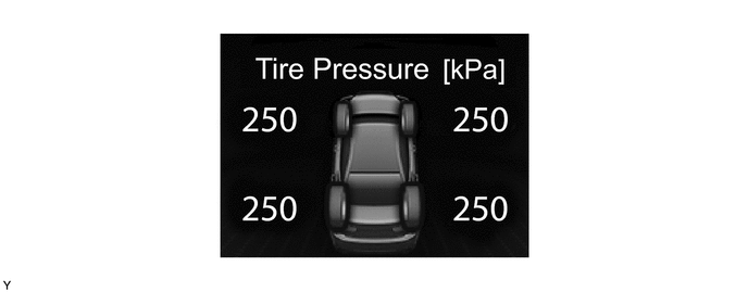
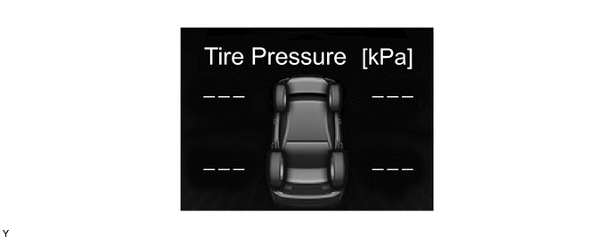
Figure 2. Tire Position Identification has Not Yet been Completed
-
Description of Tire Position Identification
-
The tire pressure warning valve and transmitter on each wheel sends the ID code, tire pressure and tire rotational period to the tire pressure warning ECU and receiver.
-
The skid control ECU inputs signals from the speed sensor on each wheel and sends a wheel speed pulse signal for each wheel to the tire pressure warning ECU and receiver.
-
The tire pressure warning ECU and receiver determines which tire (front/rear, right/left) an ID code is from based on rotation signals from the tire pressure warning valve and transmitter and wheel speed pulse signals from the skid control ECU.
-
The tire position can be identified using either of the following methods:
-
Using the Global TechStream (GTS), manually enter the tire position for each transmitter ID.
-
Perform initialization to clear the existing tire position information, then drive the vehicle at 40 km/h (25 mph) or more for 10 to 30 minutes until each tire position is automatically identified.
-
-
-
-
Warning Function
-
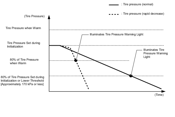
When any of the following conditions are met, the tire pressure warning system illuminates the tire pressure warning light to warn the driver.
-
When the tire pressure decreases to approximately 80% or less of the default tire pressure set during system initialization.
-
When the tire pressure decreases rapidly and drops below approximately 80% or less of the tire pressure when warm.
-
When driving for a certain period of time after the system has been initialized, the system corrects the tire pressure set during initialization according to the vehicle driving conditions and sets the tire pressure when warm.
-
The tire pressure warning pressure (pressure at which the tire pressure warning light is illuminated) cannot be set to approximately 80% or less of a specified tire pressure value.
-
The value that is approximately 80% of the set tire pressure during initialization*1 and the lower limit threshold value*2 are both displayed on the Global TechStream (GTS), and the higher of the 2 values is set as the tire pressure warning threshold value.
Tech Tips
*1: Global TechStream (GTS) data list item "Initial Threshold of Low-pressure"
*2: Global TechStream (GTS) data list item "Threshold of Low-pressure (Lower Limit)"
Note
If the tire pressure is decreased in order to adjust the tire pressure, even if the adjusted tire pressure is 80% or more than the tire pressure set during system initialization, the tire pressure warning light may illuminate if the tire pressure drops below 80% of the tire pressure set when the tires are warmed. In this case, perform initialization again.
-
-
The tire pressure warning system has 2 warning methods that are used, depending on the condition detected.
-
The table below shows the warning methods for the tire pressure warning light and multi-information display in the combination meter assembly:
Detection Condition Tire Pressure Warning Light Multi-information Display The tire pressure warning system has detected that the tire pressure has become lower than the warning threshold. Illuminates*1 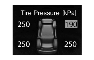
The tire pressure warning system has detected a malfunction in the system. Illuminates after blinking for 1 minute*2 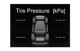
Tech Tips
*1: If the tire pressure warning light illuminates, adjust the tire pressure.
*2: If the tire pressure warning light stays on after blinking for 1 minute, the system is malfunctioning and must be repaired in order to turn off the light. For details, refer to the Repair Manual.
-
-
Initial Check Function
-
After the engine switch (push start switch) is turned on (IG), the tire pressure warning ECU and receiver illuminates the tire pressure warning light for 3 seconds to check the warning light circuits.
-
-
Initialization Function
-
By operating the steering pad switch assembly, the tire pressure warning ECU and receiver can be set to issue a warning at an inflation pressure that corresponds to the type of tires fitted to the vehicle. Therefore, the warning threshold must be set to the proper value in order to comply with local regulations.
-
Operate the steering pad switch assembly only after the inflation pressures of all tires (except the compact spare tire) have been adjusted on the vehicle.
-
During initialization, the tire pressure warning valve and transmitters measure the inflation pressure of the tires, and register the signals that are transmitted into the tire pressure warning ECU and receiver at a frequency of approximately once per minute. The initialization process is completed when signals from all tires (except the compact spare tire) have been received.
-
Perform initialization in the following cases:
-
Before delivery of a new vehicle.
-
After replacement of the tire pressure warning ECU and receiver.*
-
After replacement of a tire pressure warning valve and transmitter.*
-
When the tire pressure is adjusted.
-
When the specified tire pressure changes due to the use of a different size or type of tire.
-
When the specified tire pressure changes due to a change in the vehicle load, the speed range that the vehicle will be used in, etc.
-
When a tire rotation is performed and the specified tire pressures are different for the front and rear of the vehicle.
*: Perform initialization after the transmitter ID registration is completed.
-
-
After the initialization operation has completed, the tire pressure warning ECU and receiver receives an initialization signal and the tire pressure warning light flashes 3 times.
-
Before performing initialization, adjust the tire inflation pressure to the recommended pressure when the tires are cold. For details, refer to the Repair Manual.
-
-
-
DIAGNOSIS
-
To inform the driver when the tire pressure warning ECU and receiver detects a malfunction in the system, the tire pressure warning ECU and receiver blinks the tire pressure warning light for 1 minute, after which the light stays on. The tire pressure warning ECU and receiver also stores Diagnostic Trouble Codes (DTCs) in memory.
-
5-digit DTCs can be read by connecting the Global TechStream (GTS) to the DLC3. For details, refer to the Repair Manual.
-