ADAPTIVE VARIABLE SUSPENSION SYSTEM
-
FUNCTION OF MAIN COMPONENTS
Component Function Absorber Control ECU (with Built-in Acceleration Sensor)
-
Estimates the condition of the vehicle in accordance with the signals provided by the sensors and switches, and outputs control signals to the absorber control actuators.
-
Detects the vertical acceleration rate of the body.
Shock Absorber Assembly Absorber Control Actuator Changes the damping force of the shock absorber assembly. Driving Support ECU Assembly*1 Makes a request for damping force control to the absorber control ECU. Brake Actuator Assembly Skid Control ECU Sends the wheel speed signal, target acceleration and deceleration speed signal, damping force cooperative control signal and brake pedal depression signal to the absorber control ECU. ECM Sends the target drive force signal to the skid control ECU. Front Steering Control ECU*2 Sends the target front wheel turning angle signal to the absorber control ECU. Central Gateway ECU (Network Gateway ECU) Relays and transmits each CAN communication data signal. Acceleration Sensor Detects the vertical acceleration rate of the body. Height Control Sensor Sub-assembly Detects increases and decreases in the vehicle height. Steering Sensor Detects the steering direction and the angle of the steering wheel. Yawrate Sensor (with Built-in Deceleration Sensor) Detects the vehicle's longitudinal and lateral acceleration and deceleration. Speed Sensor Detects the wheel speed. Stop Light Switch Assembly Detects when the brake pedal is depressed. Satellite Switch Set Drive Mode Select Switches the driving mode. Combination Meter Assembly Drive Mode Indicator Displays the selected condition of the drive mode select. *1: Models with pre-collision system
*2: Models with LDH system
-
-
SYSTEM CONTROL
-
The absorber control ECU receives signals from the sensors and switches to control the absorber control actuators. The ECU uses these signals to optimally control the damping force in accordance with the driving conditions and road conditions.
-
In general, the lower the shock absorber damping force, the more that vibrations from rugged roads are absorbed to improve riding comfort. However, vehicle movements increase when driving at high speeds, braking or turning, and vibration suppression worsens when driving on uneven road surfaces or passing over large differences in height. Therefore, when driving on rough roads, the system decreases the damping force to improve riding comfort, and when large vehicle movements exist (sprung resonance), the system increases the damping force according to road conditions. Also, the system increases the damping force according to driving operations in order to ensure driving stability (a flat and stable drive) while turning.
-
The AVS effects the following controls:
Control Outline Vehicle Speed Sensing Control The system controls damping force in accordance with vehicle speed, aiming for both ride comfort at low speed and stability (a flat and stable drive) at high speed. Anti-pitch Control The system predicts the vehicle squat condition during acceleration and the dive condition during deceleration and performs control to increase the damping force, reducing changes in vehicle posture and ensuring a flat feeling and stability. Roll Posture Control The system controls the damping force to optimize the vehicle posture during turning to achieve both a vehicle posture that appeals to people's sensibilities and pleasant handling. Repercussion Control (Sprung Speed Proportional Control) Based on acceleration sensor signals, the system detects vibrations that occur in the heave, roll and pitch directions as a result of input from the road surface. Based on height sensor signals, the system detects the expansion and contraction direction of the shock absorbers. As a result, fine-grained control of the damping forces of the 4 wheels is performed to naturally dampen large vehicle movements, achieving pleasant riding comfort and a superior flat feeling. Roughness Sensing Control The system detects the unpleasant vibrations that occur when driving on rough roads based on acceleration sensor signals, and performs control to decrease the damping force. As a result, the rough feeling is eased to ensure riding comfort. Unsprung Damping Control The system detects unsprung resonance based on height control sensor signals and performs control to increase the damping force. As a result, unsprung resonance (clattering) is suppressed to ensure the road contact performance of the tires. VSC Operation Control The system appropriately controls the damping force according to whether the vehicle is sliding laterally and changes in the slipperiness of the road surface based on damping force cooperative control signals from the skid control ECU, improving VSC effectiveness. Pre-collision System Operation Control* When the driving support ECU assembly determines that a collision may occur, the system appropriately controls the damping force of the shock absorber based on damping force cooperative control signals. For details, see the Pre-collision System section. Damping Mode Selection The drive mode select enables the driver to select a desired damping force from the 3 modes. *: Models with pre-collision system
-
Anti-pitch Control
-
The skid control ECU calculates the target acceleration and deceleration speed signals based on the target braking force determined by brake pedal operations, etc., and the target drive force that the ECM determines from the accelerator pedal opening angle, etc., and sends them to the absorber control ECU. The absorber control ECU predicts the vehicle squat condition during acceleration and the dive condition during deceleration based on the target acceleration and deceleration speed signals sent by the skid control ECU, and performs control to increase the damping force. As a result, changes in the vehicle posture are reduced to ensure a flat feeling and a sense of stability.
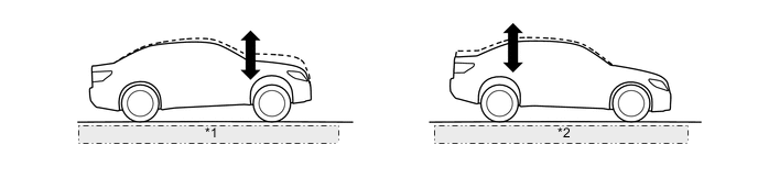
*1 Vehicle Squat Condition when Accelerating *2 Vehicle Dive Condition when Decelerating
-
-
Roll Posture Control
-
In accordance with the steering sensor and deceleration sensor signal, the damping force of each wheel is controlled to optimize the vehicle posture condition while turning.
-
Damping force is controlled to reduce the phase difference between the roll angle and pitch angle, thus achieving a vehicle posture compatible to the sensitivity of a human as well as comfortable steering.
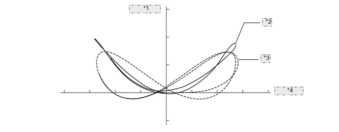
*1 Pitch Angle *2 With Control *3 Without Control *4 Roll Angle
-
-
Mode Switching Function
-
The function automatically switches the damping force control mode between the 3 types selected by drive mode select operations: "Sport", "Normal" and "Comfort".
Drive Mode Damping Force Control Mode Outline Normal Normal Achieves a good balance of high-level steering response, flat feeling, sense of stability and riding comfort. Eco Sport S Sport S+ Sport Mainly uses the hard damping force range to further emphasize steering response, flat feeling and stability, achieving sporty driving. Comfort Comfort Mainly uses the soft damping force range to achieve a more comfortable ride. 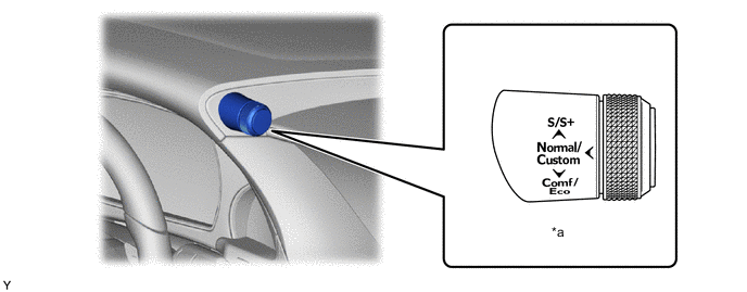
*a Drive Mode Select - -
-
-
-
FAIL-SAFE
-
If a malfunction occurs in the AVS, the absorber control ECU prohibits the damping force control.
-
-
DIAGNOSIS
-
The absorber control ECU will also store a Diagnostic Trouble Code (DTC). The DTC can be accessed through the use of a Global TechStream (GTS). For details, refer to the Repair Manual.
-