AIR SUSPENSION SYSTEM
-
CONSTRUCTION
-
The No. 1 height control valve sub-assembly and No. 2 height control valve sub-assembly close to maintain the compressed air in each pneumatic cylinder with shock absorber assembly. Also, the valves open during vehicle height control to adjust the air volume in the pneumatic cylinder with shock absorber assembly.
Figure 1. No. 1 Height Control Valve Sub-assembly
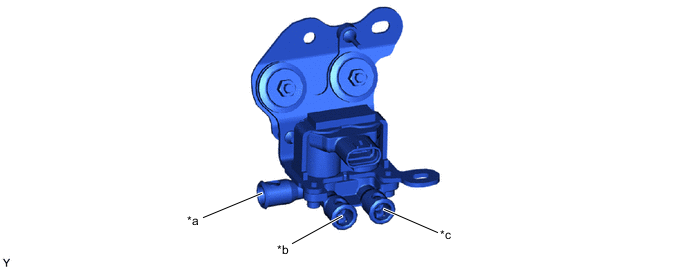
*a To Height Control Way *b To Front Pneumatic Cylinder with Shock Absorber Assembly LH *c To Front Pneumatic Cylinder with Shock Absorber Assembly RH - - Figure 2. No. 2 Height Control Valve Sub-assembly
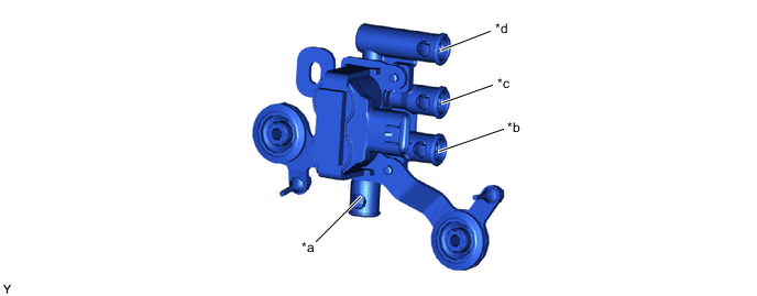
*a To Height Control Way *b To Rear Pneumatic Cylinder with Shock Absorber Assembly LH *c To Rear Pneumatic Cylinder with Shock Absorber Assembly RH *d To No. 3 Height Control Valve Sub-assembly -
The No. 3 height control valve sub-assembly switches the airflow in the system depending on the vehicle height control conditions.
Figure 3. No. 3 Height Control Valve Sub-assembly
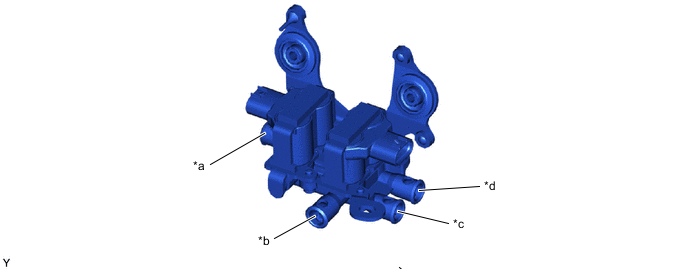
*a To Compressor Motor (Intake Side) *b To Compressor Motor (Exhaust Side) *c To Pneumatic Tank Sub-assembly *d To No. 2 Height Control Valve Sub-assembly
-