AIR SUSPENSION SYSTEM
-
CONSTRUCTION
-
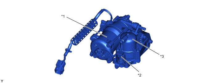
The compressor and dryer assembly is composed of a No. 1 height control compressor, No. 3 height control valve sub-assembly, height control compressor bracket and height control compressor thermistor assembly.
-
A 2-stage structure is used for vibration prevention in consideration of quietness and damping performance.
-
The height control compressor thermistor assembly detects the temperature near the compressor motor.
Figure 1. Compressor and Dryer Assembly

*1 No. 1 Height Control Compressor *2 No. 3 Height Control Valve Sub-assembly *3 Height Control Compressor Bracket *4 Height Control Compressor Thermistor Assembly *a Front Vibration Prevention Structure (1st Stage) *b Vibration Prevention Structure (2nd Stage) *c Rear Vibration Prevention Structure (1st Stage) *d Cross Sectional Diagram of Vibration Prevention Structure (2nd Stage) *e Cross Sectional Diagram of Front Vibration Prevention Structure (1st Stage) *f Cross Sectional Diagram of Rear Vibration Prevention Structure (1st Stage)
-
-
The No. 1 height control compressor is composed of a compressor motor, dryer and height control exhaust valve.
-
The compressor motor creates compressed air required for vehicle height control.
-
The dryer removes moisture in the compressed air created by the compressor motor.
-
The height control exhaust valve opens to discharge the compressed air in the system, including the air inside the pneumatic tank assembly and pneumatic cylinder with shock absorber assembly.
Figure 2. No. 1 Height Control Compressor
*1 Compressor Motor *2 Height Control Exhaust Valve *3 Dryer - -
-
-