ACTIVE STABILIZER SUSPENSION SYSTEM
-
CONSTRUCTION
-
The front and rear active stabilizer control actuator assemblies are located axially along the front and rear stabilizer bars.
-
The front and rear active stabilizer control actuator assemblies consist of components such as a motor and a reduction mechanism.
Figure 1. Front Active Stabilizer Control Actuator Assembly
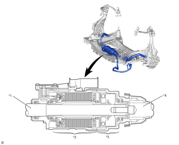
*1 Stabilizer Bar (Right side) *2 Motor *3 Reduction Mechanism *4 Stabilizer Bar (left side) Figure 2. Rear Active Stabilizer Control Actuator Assembly
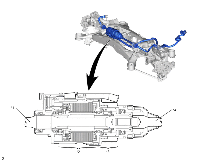
*1 Stabilizer Bar (Right side) *2 Motor *3 Reduction Mechanism *4 Stabilizer Bar (left side)
-
Reduction Mechanism
-
The reduction mechanism uses strain wave gearing, which is compact and highly accurate, and creates a large reduction gear ratio (1:200) using a small number of components.
-
The reduction mechanism consists of a wave generator, a flexible gear and a circular gear.
Construction of Reduction Mechanism Item Construction Wave Generator (Input)
-
Consists of an oval-shaped cam, and a ball bearing that is fitted around the cam.
-
Coupled to the motor shaft of the motor, and rotates inside the flexible gear.
Flexible Gear (Output)
-
Consists of an elastic metal outer circumference that has 400 teeth and a spline coupled to the stabilizer bar (Right side).
-
Located on the outside of the wave generator, the flexible gear meshes with the circular gear while undergoing elastic deformation from the rotational movement of the wave generator.
Circular Gear (Output)
-
Consists of a housing inner circumference that has 402 teeth and a spline coupled to the stabilizer bar (left side).
-
Located on the outside of the flexible gear, the circular gear meshes with the major axis of the flexible gear via the rotational movement of the wave generator.
Figure 3. Rear Active Stabilizer Control Actuator Assembly
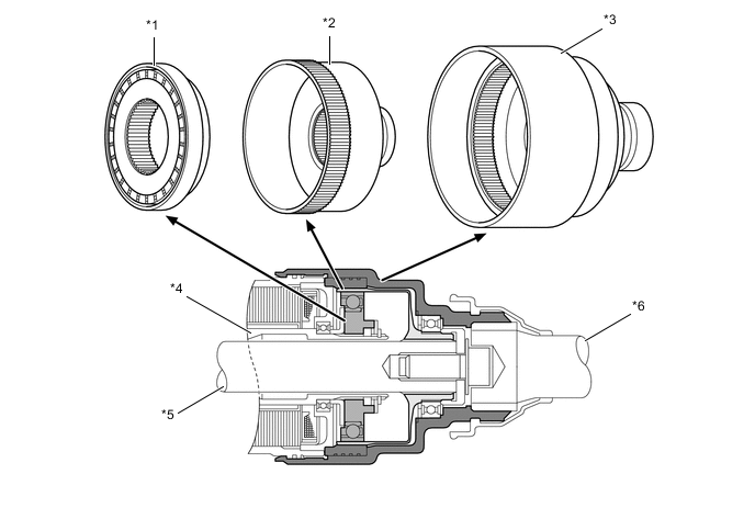
*1 Wave Generator *2 Motor *3 Circular Gear *4 Motor Shaft *5 Stabilizer Bar (Right side) *6 Stabilizer Bar (left side) -
-
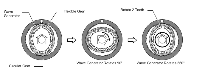
The flexible gear is fitted inside the circular gear. Furthermore, the wave generator is fitted inside the flexible gear. The rotational movement of the wave generator causes the flexible gear to become deformed into an oval shape. The teeth of the major axis mesh with the circular gear, and the teeth of the minor axis separate from the circular gear.
-
When the circular gear is fixed and the wave generator rotates clockwise, the flexible gear undergoes an elastic deformation. This results in the position of the meshing of the teeth being moved with the circular gear.
-
The flexible gear has 2 fewer teeth than the circular gear. Therefore, with each rotation of the wave generator, the flexible gear rotates 2 teeth counterclockwise, which is opposite to the rotational direction of the wave generator. This rotational difference is taken out as an output.
-
Due to the aforementioned principle, when the motor rotates clockwise, the rotational movement of the wave generator causes the flexible gear to rotate counterclockwise. This rotation causes a rotational difference between the stabilizer bar (Right side) coupled to the flexible gear and the stabilizer bar (left side) coupled to the circular gear, thus changing the twist angle of the stabilizer bars.
Figure 4. Rear Active Stabilizer Control Actuator Assembly
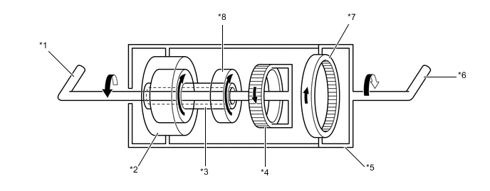
*1 Stabilizer Bar (Right side) *2 Motor *3 Motor Shaft *4 Flexible Gear *5 Motor Housing *6 Stabilizer Bar (left side) *7 Circular Gear *8 Wave Generator
-
-
Motor
-
A compact, high power output and low noise brushless type motor is used.
-
The motor is composed of a coil, magnet, motor shaft and rotation angle sensor.
-
The motor shaft is coupled to the wave generator, and the motor housing is coupled to the circular gear.
-
The rotation angle sensor detects the motor rotation angle. A resolver sensor is used to precisely control the motor rotation, achieving precise and smooth control.
Figure 5. Motor Cross Section (Front Active Stabilizer Control Actuator Assembly)
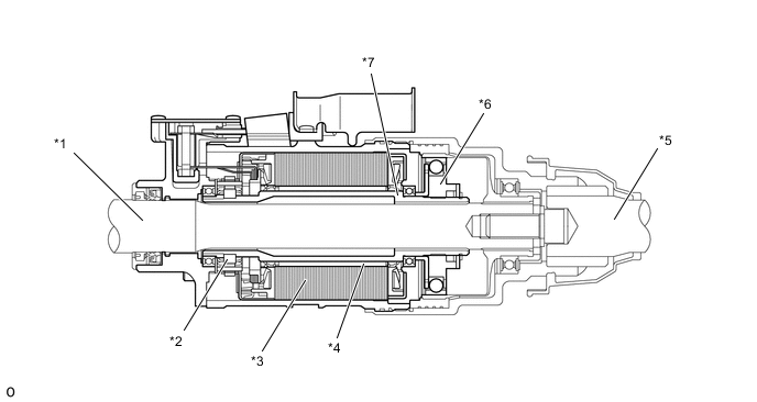
*1 Stabilizer Bar (Right side) *2 Rotation Angle Sensor *3 Coil *4 Magnet *5 Stabilizer Bar (left side) *6 Wave Generator *7 Motor Shaft - - -
-