ACTIVE STABILIZER SUSPENSION SYSTEM
-
FUNCTION OF MAIN COMPONENTS
Component Function Active Stabilizer Control ECU Assembly Controls the front active stabilizer control actuator assembly according to stabilizer bar twisting angle signals from the front steering control ECU and skid control ECU. Rear Active Stabilizer Control ECU Assembly Controls the rear active stabilizer control actuator assembly according to stabilizer bar twisting angle signals from the front steering control ECU and skid control ECU. Front Active Stabilizer Control Actuator Assembly Rotation Angle Sensor Outputs motor rotation angle signals to the active stabilizer control ECU assembly. Motor Rotates and operates the deceleration mechanism according to operation signals from the active stabilizer control ECU assembly. Reduction Mechanism Operates according to motor rotation and twists the left and right stabilizer bars connected to the front active stabilizer control actuator assembly. Rear Active Stabilizer Control Actuator Assembly Rotation Angle Sensor Outputs motor rotation angle signals to the rear active stabilizer control ECU assembly. Motor Rotates and operates the deceleration mechanism according to operation signals from the rear active stabilizer control ECU assembly. Reduction Mechanism Operates according to motor rotation and twists the left and right stabilizer bars connected to the rear active stabilizer control actuator assembly. Power Steering ECU with Motor Assembly Power Steering ECU Controls the power steering system according to VDIM cooperative control request signals from the skid control ECU. Absorber Control ECU Controls the AVS according to VDIM cooperative control request signals from the skid control ECU. ECM Controls the drive force according to VDIM cooperative control request signals from the skid control ECU. Steering Sensor Detects the steering direction and the angle of the steering wheel. Yawrate Sensor (with Built-in Deceleration Sensor)
-
Detects the vehicle's yaw rate.
-
Detects the vehicle's longitudinal and lateral acceleration.
Front Steering Control ECU
-
Calculates the target front wheel turning angle based on the steering angle signal and vehicle speed signal and drives the motor of the steering actuator assembly.
-
Calculates the target rear wheel turning angle based on the steering angle signal and vehicle speed signal and sends the result to the rear steering control ECU.
-
Calculates the target stabilizer bar twisting angle based on the steering angle signal and vehicle speed signal and sends it to the active stabilizer control ECU assembly and rear active stabilizer control ECU assembly.
-
Further calculates the target stabilizer bar twisting angle, which was calculated by the skid control ECU, and sends the result to the active stabilizer control ECU assembly and rear active stabilizer control ECU assembly.
Rear Steering Control ECU Drives the motor of the rear steering link assembly in accordance with the target rear wheel turning angle signal from the front steering control ECU. Brake Actuator Assembly Skid Control ECU
-
Calculates the target stabilizer bar twisting angle based on signals from ECUs and sensors and sends it to the front steering control ECU.
-
Sends the vehicle speed signal and VDIM cooperative control request signal to the ECUs.
Combination Meter Assembly Multi-information Display Displays a message when a system malfunction occurs. Master Warning Light Illuminates together with the message on the multi-information display when a system malfunction occurs. Buzzer Sounds together with the message on the multi-information display when a system malfunction occurs. -
-
SYSTEM CONTROL
-
The active stabilizer suspension system is constantly and comprehensively controlled by VDIM. In the normal range, the front steering control ECU calculates the stabilizer bar twisting angle and sends it to the active stabilizer control ECU assembly and rear active stabilizer control ECU assembly via CAN communication. In the limit range, the skid control ECU calculates the stabilizer bar twisting angle and sends it to the front steering control ECU via CAN communication. The front steering control ECU further calculates the target stabilizer bar twisting angle, which was calculated by the skid control ECU, and sends the result to the active stabilizer control ECU assembly and rear active stabilizer control ECU assembly via CAN communication.
-
The active stabilizer control ECU assembly controls the front active stabilizer control actuator assembly and the rear active stabilizer control ECU assembly controls the rear active stabilizer control actuator assembly according to the stabilizer bar twisting angle signal calculated by the front steering control ECU.
-
Normal Range Control
-
The front steering control ECU uses sensors and ECUs to detect body roll movements according to driver steering operations and road surface inputs and calculates the optimal stabilizer bar twisting angle. The active stabilizer control ECU assembly controls the front active stabilizer control actuator assembly and the rear active stabilizer control ECU assembly controls the rear active stabilizer control actuator assembly based on the calculated optimal stabilizer bar twisting angle, reducing roll movements.
-
Roll control, performed by the active stabilizer suspension system, and cooperative control with other systems, performed by VDIM, achieve comfortable performance through responsive vehicle movement performance according to driver steering operations and a flat vehicle posture.
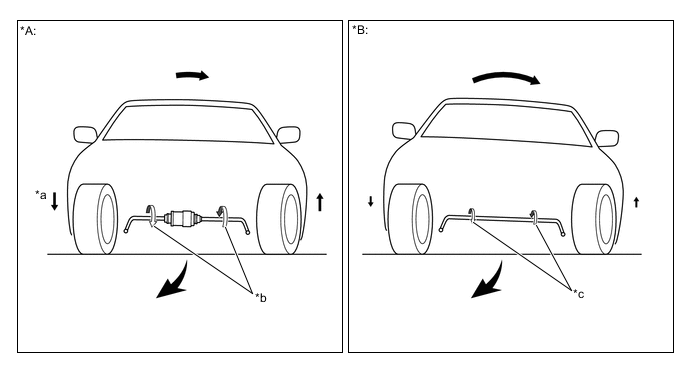
*A Models with Active Stabilizer Suspension System *B Models without Active Stabilizer Suspension System *a Movement of Vehicle Body Caused by Twisting of Active Stabilizer Actuator Assembly *b Twist of Stabilizer Bar Caused by Active Stabilizer Actuator Assembly Activation *c Reaction Force Proportional to Spring Constant of Stabilizer Bar - -
-
-
Limit Range Control
-
The skid control ECU detects the tire slip condition using sensors and ECUs and calculates the stabilizer bar twisting angle necessary for increasing the tire contact load when driving on split friction road surfaces. The active stabilizer control ECU assembly controls the front active stabilizer control actuator assembly and the rear active stabilizer control ECU assembly controls the rear active stabilizer control actuator assembly based on the calculated stabilizer bar twisting angle, increasing the tire contact load.
-
Tire contact load increasing control, performed by the active stabilizer suspension system, and cooperative control with other systems, performed by VDIM, support safer and more pleasant driving (driving, turning and stopping) in the limit range.
-
In addition, the active stabilizer suspension system is used when accelerating on split friction roads to increase the contact load on the side that transmits larger amounts of drive force according to the road surface and operation condition and efficiently transmit drive force to the road surface. As a result, active stabilizer suspension system control is added to the control of other systems performed by VDIM, making it possible to achieve a higher level of stability and acceleration performance.
Figure 1. Split Friction Road Acceleration Control
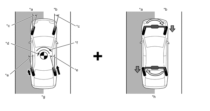
*a Low Friction Road *b High Friction Road *c Front Wheel Steering Control *d Moment Generated due to Difference between Drive Force of Left and Right Wheels *e Rear Wheel Steering Control *f Stabilizing Moment Generated due to Steering Control *g Control of Other Systems (Brake Control System, Power Assist System and LDH System) according to VDIM *h Active Stabilizer Suspension System Control 
Drive Force 
Contact Load Movement 
Increases Contact Load - - -
When braking on split friction roads, the active stabilizer suspension system is used to increase the contact load of the rear wheel on the side with a higher friction coefficient and more effectively use the tire performance of the rear wheel. As a result, active stabilizer suspension system control is added to the control of other systems performed by VDIM, making it possible to achieve a higher level of stability and braking performance.
Figure 2. Control when Braking on Split Friction Road
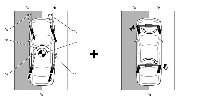
*a Low Friction Road *b High Friction Road *c Front Wheel Steering Control *d Stabilizing Moment Generated due to Steering Control *e Rear Wheel Steering Control *f Moment Generated due to Difference between Brake Force of Left and Right Wheels *g Control of Other Systems (Brake Control System, Power Assist System and LDH System) according to VDIM *h Active Stabilizer Suspension System Control Brake Force Contact Load Movement Increases Contact Load - -
-
-
-
FUNCTION
-
The function automatically switches the control mode between the 3 types selected by drive mode select operations: "Sport", "Normal" and "Comfort".
Drive Mode Control Mode Outline Normal Normal Provides vehicle response according to the driver's intentions and pleasant driving comfort that cuts off input from the road surface. Eco Sport S Sport S+ Sport Varies the characteristics of the active stabilizer suspension system and controls roll movement according to steering wheel operations. This mode achieves levels of vehicle response to driver's intentions, stable vehicle posture and pleasant driving comfort that surpass those provided by normal mode. Comfort Comfort Suppresses the roll posture of the rear seats using the active stabilizer suspension system and achieves vehicle movement that further emphasizes rear seat comfort in a manner appropriate for a flagship model. 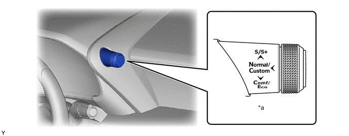
*a Drive Mode Select - -
-
-
FAIL-SAFE
-
The fail-safe function operates when a system malfunction occurs. At this time, the master warning light in the combination meter assembly illuminates, a message is displayed on the multi-information display and the buzzer sounds to inform the driver of a system malfunction.
-
-
DIAGNOSIS
-
A diagnostic function has been provided to simplify system inspections. For diagnosis troubleshooting procedures and items, refer to the Repair Manual.
-